Showing posts with label WDM. Show all posts

Wednesday, July 20, 2016

A Wise Decision to Choose DWDM Mux/DeMux

The advent of big data requires for highly efficient and capable data transmission speed. To solve the paradox of increasing bandwidth but spending less, WDM (wavelength division multiplexing) multiplexer/demultiplexer is the perfect choice. This technology can transport extremely large capacity of data traffic in telecom networks. It’s a good way to deal with the bandwidth explosion from the access network.
WDM
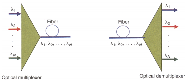
WDM stands for wavelength division multiplexing. At the transmitting side, various light waves are multiplexed into one single signal that will be transmitted through an optical fiber. At the receiver end, the light signal is split into different light waves. There are 2 standards of WDM: coarse wavelength division nultiplexing (CWDM) and dense wavelength division multiplexing (DWDM). The main difference is the wavelength steps between the channels. For CWDM this is 20nm (course) and for DWDM this is typically 0.8nm (dense). The following is going to introduce DWDM Mux/Demux.
DWDM Technology
DWDM technology works by combing and transmitting multiple signals simultaneously at different wavelengths over the same fiber. This technology responds to the growing need for efficient and capable data transmission by working with different formats, such as SONET/SDH, while increasing bandwidth. It uses different colors (wavelength) which are combined in a device. The device is called a Mux/Demux, abbreviated from multiplexer/demultiplexer, where the optical signals are multiplexed and de-multiplexed. Usually demultiplexer is often used with multiplexer on the receiving end.
Mux/Demux
Mux selects one of several input signals to send to the output. So multiplexer is also known as a data selector. Mux acts as a multiple-input and single-output switch. It sends optical signals at high speed over a single fiber optic cable. Mux makes it possible for several signals to share one device or resource instead of having one device per input signals. Mux is mainly used to increase the amount of data that can be sent over the network within a certain amount of time and bandwidth.
Demux is exactly in the opposite manner. Demux is a device that has one input and more than one outputs. It’s often used to send one single input signal to one of many devices. The main function of an optical demultiplexer is to receive from a fiber consisting of multiple optical frequencies and separate it into its frequency components, which are coupled in as many individual fibers as there are frequencies.

DWDM Mux/Demux modules deliver the benefits of DWDM technology in a fully passive solution. They are designed for long-haul transmission where wavelengths are packed compact together. FS.COM can provide modules for cramming up to 48 wavelengths in 100GHz grid(0.8nm) and 96 wavelengths in 50GHz grid(0.4nm) into a fiber transfer. ITU G.694.1 standard and Telcordia GR1221 are compliant. When applied with Erbium Doped-Fiber Amplifiers (EDFAs), higher speed communications with longer reach (over thousands of kilometers) can be achieved.
Currently the common configuration of DWDM Mux/Demux is from 8 to 96 channels. Maybe in future channels can reach 200 channels or more. DWDM system typically transports channels (wavelengths) in what is known as the conventional band or C band spectrum, with all channels in the 1550nm region. The denser channel spacing requires tighter control of the wavelengths and therefore cooled DWDM optical transceiver modules required, as contrary to CWDM which has broader channel spacing un-cooled optics, such as CWDM SFP, CWDM XFP.
DWDM Mux/Demux offered by FS.COM are available in the form of plastic ABS module cassette, 19” rack mountable box or standard LGX box. Our DWDM Mux/Demux are modular, scalable and are perfectly suited to transport PDH, SDH / SONET, ETHERNET services over DWDM in optical metro edge and access networks. FS.COM highly recommends you our 40-CH DWDM Mux/DeMux. It can be used in fiber transition application as well as data center interconnection for bandwidth expansion. With the extra 1310nm port, it can easily connect to the existing metro network, achieving high-speed service without replacing any infrastructure.

Conclusion
With DWDM Mux/DeMux, single fibers have been able to transmit data at speeds up to 400Gb/s. To expand the bandwidth of your optical communication networks with lower loss and greater distance capabilities, DWDM Mux/DeMux module is absolutely a wise choice. For other DWDM equipment, please contact via sales@fs.com.
Originally published at www.fiber-optic-equipment.com

Friday, August 28, 2015

EDFA — the Most Popular Optical Amplifier in Optical Communications

There will be attenuation losses in the fiber when the signals transmit over long distances. To compensate for the attenuation losses, optical amplifier which could restore the optical signal to its original power level without E-O and O-E (electrical to optical and optical to electrical) conversions is needed. Optical amplifier is an important enabling technology for optical communication networks. There are three common optical amplifiers which include erbium-doped fiber amplifier (EDFA), the semiconductor optical amplifier (SOA), and the Raman amplifier. Among them EDFA is most often applied in optical communications.
Definition
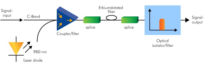
EDFA uses a short length of optical fiber doped with the rare-earth element erbium that has the appropriate energy levels in the atomic structures for amplifying optical signal. It’s designed to amplify light at wavelengths around 1550 nm and make wavelengths suffer minimum attenuation in optical fibers. EDFA often uses a 980nm or 1480nm pump laser to inject energy into the doped fiber. The 980nm band has a higher absorption cross-section and is generally used for low-noise performance. The 1480nm band has a lower but broader absorption cross-section and is generally used for high power amplifiers.
Principle of EDFA
The principle of EDFA is shown as the following picture. EDFA usually consists of a length of EDF (erbium-doped fiber), a pump laser, and a component (often known as a WDM coupler) for combining the signal and pump wavelength and an isolator. The pump laser, known as pumping bands, inserts dopants into the silica fiber and makes erbium enter into an excited state. When the weak signals at 1310 nm or 1550 nm travel through the fiber, the lights will stimulate the excited atoms of erbium so that the atoms can release energy in the form of photons. The emitted light photons which have the same wavelength with input signals amplify the optical signals. The signals passing by the fiber will grow stronger and stronger. And the function of the isolator usually placed at the output is to prevent reflections returning from the attached fiber. Because the reflections can disrupt amplifier operation. Thus, EDFA is a high gain amplifier.
Applications
EDFA has many useful functions in telecom systems for fiber communications. For instance, it can boost the power of a data transmitter before entering a long fiber span. It could also be used in front of a data receiver if the arriving signal is weak. What’s more, an EDFA can be used to maintain extended spans of passive transmission fiber. So that the transmission losses through the long distance fiber could be compensated. EDFA is oftern applied in DWDM, CATV, SDH. In addition, an EDFA could be used as the equipment for testing transmission hardware.
Conclusion
In long distance communications, the signals should be amplified to avoid the attenuation losses. There are many kinds of optical amplifiers could be used to amplify the signal but some of them are not very often applied because of certain obvious disadvantages. For example, SOA will add noise to the signal. While EDFA has some interesting properties for fiber optics communications due to its rare-earth element. EDFA is a low-noise amplifier which can simultaneously amplify many data channels at different wavelengths with flat gain, high saturation output power and stable operation. So these advantages make EDFA the most popular in optical communication applications.
Originally published at http://www.china-cable-suppliers.com/

Friday, August 14, 2015

Introduction for Optical Add-Drop Multiplexer

The evolution of single wavelength point-to-point transmission lines to wavelength division multiplexing optical networks arose the need to separate/route different wavelength channels. What kind of device can meet this need? The answer is optical add-drop multiplexer (OADM). This device is used for multiplexing and routing different channels of light into or out of a single mode fiber (SMF). “Add” means adding one or more new wavelength channels to an existing multi-wavelength WDM signal. “Drop” means dropping or removing one or more channels, passing those signals to another network path. OADM is particularly important in metropolitan WDM lightwave services where offices or sites can be connected by different add-drop channels. It can increase the network flexibility along the optical link.
Principle
A traditional OADM has three stages: an optical multiplexer, and optical demultiplexer, and between them a method of reconfiguring the paths and a set of ports for adding and dropping signals. The multiplexer is to couple two or more wavelengths into the same fiber. The reconfiguration can be achieved by a fiber patch or by optical switches which direct the wavelengths to the add ports. The demultiplexer separates wavelengths in a fiber and direct them into many fibers.
OADM-WDM-CWDM
Add-Drop Configurations
To realize the configurations performance of adding or dropping functions, planar and fiber technology could be used. No matter what kind of devices, several factors should be considered, such as low insertion loss, high isolation, polarization insensitivity, and the cost. Planar devices provide compact solutions with the possibility of adding or dropping many channels using only one integrated optical circuit with arrayed-waveguide-grating or waveguide-grating-router. But they have the main disadvantages of high insertion loss and polarisation dependence. Comparatively, all-fiber devices are more attractive because of the low insertion losses, polarisation insensitivity and ease of coupling between output and input of the optical network by using simple splices and pigtails. But these devices are sensitive to environmental variations. There is another kind of devices based on free space optics (micro mirrors and gratings) also used to perform add-drop operations well. However, these devices have high insertion losses and cost much. So thin film filter devices have been used for multiplexing/demultiplexing applications.
Types
OADM have passive modes with fixed wavelength (COADM) and active modes with dynamic wavelength (ROADM). In fixed wavelength OADM, the wavelength has been selected and remains the same until people change it. In dynamic wavelength OADM, the wavelengths could be directed selectively without changing its physical configuration. Different types have different functions. For the OADM with fixed wavelengths, the node’s routing is determined but is not flexible. For the OADM with dynamic wavelengths, it’s more flexible but cost too much.
OADM selectively drops a required wavelength from multiple wavelengths in a fiber and adds the same wavelength into the data flow but with different data content. It’s used in both CWDM systems and DWDM systems. CWDM OADM is designed for the CWDM passive optical systems. It can add/drop wavelengths from multiple fibers onto one optical fiber. And DWDM OADM is designed to add/drop one multiple DWDM channels into one or two fibers. Although OADM is good enough to use, it is still under improvement. In the future,  it will be more cost-effective.
Originally published at http://www.china-cable-suppliers.com/