Increasing bandwidth has always been the most important task of telecom engineers. Through decades of research and engineering effort, 40Gbps and 100Gbps solutions have been used for network applications. But 40G and 100G transceivers can’t support too much long distance (QSFP-40G-ER4 for 40 km, QSFP-100G-LR4 for 10 km). How to extend the 500Gbps link to thousands of kilometers in Metro network within limited budget?
Save Fiber Cost–500Gbps Over Single Fiber Cable
Fiber cable cost takes a certain percentage in the whole network budget. Point to point connection needs many cables, while WDM technology take well care of this issue. In a metro network, usually multiple 10Gbps signals are transmitted by the use of DWDM Mux/Demux over a single fiber cable, which can save lots of money on multiple fiber cables and cable management issues. Then how to save cost to transmit 500Gbps signals over single fiber cable?
It sounds unbelievable. But we have the cost-effective solution. As we know, it will cost too much to replace all the current network system for upgrading to higher data rate. To save cost for increasing bandwidth, some producers add an extra port on DWDM Mux/Demux and that is 1310nm or 1550nm port. This port supports 1310nm or 1550nm transceiver. With such port, you can add 1G/10G/40G/100G to the existing DWDM network. For instance, we use 40-channel C21-C60 dual fiber DWDM Mux/Demux with 1310nm port and 1310nm band port for 1G/10G/40G/100G “grey” light. Plug 10G DWDM SFP+ transceivers into 40 channels, the overload is 400Gbps. Once plugging a 1310 40G QSFP+ LR4/ER4, then the total link reach up to 440G (400G + 40G). If install a 100G QSFP28 LR4 transceiver into 1310 port, the whole transport will be 500Gbps (400G + 100G). See this solution realize the goal of saving cost to run such huge network load over a single fiber.


Extend 500G Transmission Distance
Since 500G signals can be transmitted over a single fiber cable, we have another issue to be solved. 500G transmission distance is needed far more than few kilometers in real life, maybe thousand of kilometers. How to extend the transmission distance?
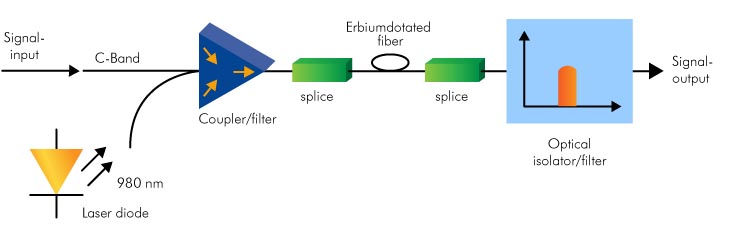
According to IEEE standard, LR4 and ER4 transceivers can support the reach of 10 km and 40 km in the in ideal conditions, not considering fiber loss or connector loss. To extend 500Gpbs transmission distance, we need SOA (Semiconductor Optical Amplifier) and EDFA (Erbium Doped Fiber Amplifier). Add an SOA to support 40G/100GBASE-LR4 transceiver (over 1310 nm). The SOA is used to amplify incoming (Rx) signal on the receiving side of the link. So that the distances can reach up to 60 km. In 10Gbps DWDM networks, the signal transmission distance can be extended to hundreds of kilometers by the use of and EDFA (Erbium Doped Fiber Amplifier).

Recommended DWDM Solutions for 500Gbps Metro Network
| ID# | FS Part Number | Description |
| 35887 | 40MDD-1RU-A1-FSDWDM | 40 Ch 1RU Duplex DWDM MUX DEMUX C21 to C60 with 1310nm Port and Monitor Port |
| 14491 | DWDM-SFP10G-40 | 10GBASE 100GHz DWDM SFP+ 40km, LC Duplex Interface, C21 to C60 |
| 31533 | DWDM-SFP10G-80 | 10GBASE 100GHz DWDM SFP+ 80km, LC Duplex Interface, C21 to C60 |
| 14599 | DWDM-XFP10G-40 | 10GBASE 100GHz DWDM XFP 40km, LC Duplex Interface, C21 to C60 |
| 14650 | DWDM-XFP10G-80 | 10GBASE 100GHz DWDM XFP 80km, LC Duplex Interface, C21 to C60 |
| 35208 | QSFP-LR4-40G | 40G QSFP+ LR4 1310nm 10km, LC Duplex Interface |
| 35210 | QSFP-ER4-40G | 40G QSFP+ ER4 1310nm 40km, LC Duplex Interface |
| 35014 | CFP2-LR4-100G | 100G CFP2 LR4 1310nm 10km, LC Duplex Interface |
| 35192 | FS-SOA-G10 | 10dB Gain 1310nm Semiconductor Optical Amplifier |
| 31366 | EDFA-BAO22 | 20dBm Output C-band 40 Channels 26dB Gain Booster EDFA |
Summary
DWDM technology is very necessary to extend Metro Network reach. In this 500Gpbs Metro network, I have introduced very detailed cost-effective solutions. Remember all the indispensable DWDM equipment such as DWDM transceivers, DWDM Mux/Demux, EDFA, etc. For more information, please visit the site about FS.COM Long Haul DWDM Network Solution.
Related articles: How to Extend 40G Connection up to 80 km?
Economically Increase Network Capacity With CWDM Mux/DeMux
Economically Increase Network Capacity With CWDM Mux/DeMux
Originally published at http://www.fiber-optic-equipment.com