Friday, August 28, 2015

EDFA — the Most Popular Optical Amplifier in Optical Communications

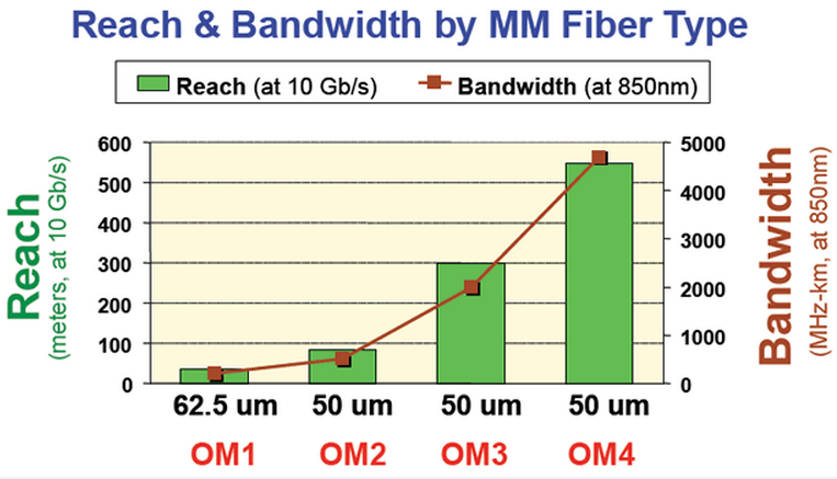
There will be attenuation losses in the fiber when the signals transmit over long distances. To compensate for the attenuation losses, optical amplifier which could restore the optical signal to its original power level without E-O and O-E (electrical to optical and optical to electrical) conversions is needed. Optical amplifier is an important enabling technology for optical communication networks. There are three common optical amplifiers which include erbium-doped fiber amplifier (EDFA), the semiconductor optical amplifier (SOA), and the Raman amplifier. Among them EDFA is most often applied in optical communications.
Definition
EDFA uses a short length of optical fiber doped with the rare-earth element erbium that has the appropriate energy levels in the atomic structures for amplifying optical signal. It’s designed to amplify light at wavelengths around 1550 nm and make wavelengths suffer minimum attenuation in optical fibers. EDFA often uses a 980nm or 1480nm pump laser to inject energy into the doped fiber. The 980nm band has a higher absorption cross-section and is generally used for low-noise performance. The 1480nm band has a lower but broader absorption cross-section and is generally used for high power amplifiers.
Principle of EDFA
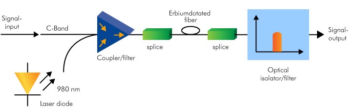
The principle of EDFA is shown as the following picture. EDFA usually consists of a length of EDF (erbium-doped fiber), a pump laser, and a component (often known as a WDM coupler) for combining the signal and pump wavelength and an isolator. The pump laser, known as pumping bands, inserts dopants into the silica fiber and makes erbium enter into an excited state. When the weak signals at 1310 nm or 1550 nm travel through the fiber, the lights will stimulate the excited atoms of erbium so that the atoms can release energy in the form of photons. The emitted light photons which have the same wavelength with input signals amplify the optical signals. The signals passing by the fiber will grow stronger and stronger. And the function of the isolator usually placed at the output is to prevent reflections returning from the attached fiber. Because the reflections can disrupt amplifier operation. Thus, EDFA is a high gain amplifier.
Applications
EDFA has many useful functions in telecom systems for fiber communications. For instance, it can boost the power of a data transmitter before entering a long fiber span. It could also be used in front of a data receiver if the arriving signal is weak. What’s more, an EDFA can be used to maintain extended spans of passive transmission fiber. So that the transmission losses through the long distance fiber could be compensated. EDFA is oftern applied in DWDM, CATV, SDH. In addition, an EDFA could be used as the equipment for testing transmission hardware.
Conclusion
In long distance communications, the signals should be amplified to avoid the attenuation losses. There are many kinds of optical amplifiers could be used to amplify the signal but some of them are not very often applied because of certain obvious disadvantages. For example, SOA will add noise to the signal. While EDFA has some interesting properties for fiber optics communications due to its rare-earth element. EDFA is a low-noise amplifier which can simultaneously amplify many data channels at different wavelengths with flat gain, high saturation output power and stable operation. So these advantages make EDFA the most popular in optical communication applications.
Originally published at http://www.china-cable-suppliers.com/

Wednesday, August 26, 2015

The Essential Mux/Demux Device in CWDM system

CWDM is short for coarse wavelength division multiplexing. CWDM technology is a method of combining multiple signals on laser beams at various wavelengths for transmission along a single fiber optic cable. CWDM system provides channels like 4, 8, 12 and 16 with the spacing of 20nm. The spectrum grid can remain from 1270nm to 1610nm when multiple wavelengths added to one fiber. It’s a cost effective choice for transporting large amounts of data traffic in telecoms or enterprise networks. Because CWDM can increase a fiber network capacity without deploying more fiber cables thus avoid fiber exhaust.
As mentioned above, CWDM is used to increase the amount of information that can be transmitted over a single fiber. Then the optical wavelength multiplexer (MUX) and the de-multiplexer (DEMUX) are indispensable components to deal with small numbers of wavelengths in this system.
What is CWDM Mux/Demux? The CWDM Mux/Demux is a device designed to allow multiple optical signals with different wavelengths to pass through a single optical fiber strand and split the multi-wavelength optical signals. For example, with a multiplexer at the beginning of the network, a typical 4 channel CWDM will be used to multiplex four different wavelengths onto one fiber. This means four different networks/systems can be transmitted over the same fiber simultaneously. At the opposite end of the network, a CWDM demultiplexer to demultiplex the wavelengths to allow them to be directed to the correct receivers. But usually CWDM Mux and Demux are integrated in an entirety. So the optical transmission is done by dual fibers where one fiber is transporting data from east to weat and vice-versa. With highly reliable passive optics certified for environmentally hardened applications, the CWDM Mux/Demux lets operators make full use of available fiber bandwidth in local loop and enterprise architectures. It’s a flexible, low cost solution that enables the expansion of existing fiber capacity.
CWDM Dux and Demux
The followings are the features of CWDM Mux/Demux:
  • Long distance coverage of multiple signals on a single fiber strand
  • Good flexibility and expansibility
  • Low end-to-end insertion loss
  • Extended operating temperature range suitable for remote office environments
  • High optical fiber transmission capacity
  • Simple to install, requires no configuration or maintenance
  • Passive CWDM optical Mux/Demux design
  • Low content delivery costs where dark fiber is available
Based on these features, CWDM Mux/Demux module can be applied in broad fields: enterprises and carriers with fiber optic infrastructure, transmitting additional applications with existing fiber cables, connecting buildings to CWDM campus ring, connecting field offices to cental office, ideal solution for metro-core, metro-access and enterprises.
Fiberstore supplies passive CWDM Mux/Demux with all channels except the common 4, 8, 16, 18 channel. All CWDM Mux/Demux modules suit Gigabit & 10G Ethernet, SDH/SONET, ATM, ESCON, Fibre Channel, FTTx and CATV, etc. And various optional port configurations are available such as Express Port, Monitor Port, 1310nm passband port and 1550nm port for these multiplexers according to your choice.
Originally published at http://www.china-cable-suppliers.com/

Friday, August 21, 2015

The Increasing Need for OM3 and OM4 Multi-mode Fiber Cable

In multi-mode fiber system, numerous modes or light rays are carried simultaneously through the waveguide. Multi-mode fiber systems offer flexible, reliable and cost effective cabling solutions for local area networks (LANs), storage area networks (SANs), central offices and data centers.
Multi-mode fibers are identified by the OM (“optical mode”) designation as outlined in the ISO/IEC 11801 standard. Today there are four types of multi-mode fiber: OM1 (62.5μm multi-mode fiber), OM2 (50μm multi-mode fiber), OM3 (laser optimized 50μm multi-mode fiber), OM4 (laser optimized 50μm multi-mode fiber). 62.5μm and 50μm mean the diameters of the glass or plastic core, the part of the fiber carrying the light which encodes the data. These different multi-mode fiber cables can support data rates from 10 and 100 Megabits per second (Mb/s) up to 1 Gigabit per second (Gb/s) and 10 Gb/s, even up to 40 Gb/s and 100 Gb/s.
62.5 μm multi-mode fiber (OM1) was introduced in 1985. OM1 fiber could support 2km campuses at 10 Mb/s. For more than a decade, 50μm multi-mode fiber (OM2) was established for both short and long distance applications with the data rates range from 10 Mb/s to 100 Mb/s.
As the need for higher data rates and longer distance increases, new transmission media must be made to meet the requirements. Thus the laser optimized multi-mode fiber cables, that is, OM3 and OM4 cables which could support higher data rates about 1Gb/s, 10Gb/s, even about 40Gb/s and 100Gb/s over longer distances than OM1 and OM2 cables are introduced.
OM3 fiber cable has a higher bandwidth to support 1 Gb/s and 10 Gb/s over longer distance. But compared with the installation cost of networks using lower bandwidth OM1 or OM2 fibers, OM3 is cost effective and saves for the electronics when upgrading to higher speeds. Besides, OM3 fiber cables share the same connector and installation techniques as 62.5 µm fiber. So the installers don’t need additional training, which will increase the cost. As a result, OM3 will be a good choice for customers in LANs, SANs, and data centers.
Like OM3, OM4 is also laser optimized multi-mode fiber with extended bandwidth. It’s designed for existing 1 and 10 Gb/s applications as well as future 40 and 100 Gb/s systems by 850nm Vertical Cavity Surface Emitting Lasers (VCSELs). Although OM2 fiber can use VCSELs, it can only reach 550 meters at 1 Gb/s and 82 meters at 10 Gb/s. While OM4 can transmit the data over 1000 meters at 1 Gb/s and 550 meters at 10 Gb/s. With its high bandwidth, OM4 will be the best solution for network designers and operators in data centers and LANs.
The booming network technology drives the need for increased data rates and fiber usage in the data center. High density optical connectivity are important to optimize cable management. Because OM3 and OM4 fiber cables are good for transporting higher data rates and they are primarily applied in the data center. OM3 and OM4 fibers continue to be improved to meet new challenges.
Originally published at http://www.china-cable-suppliers.com/

Tuesday, August 18, 2015

Simplex and Duplex Fiber Optic Cable

A fiber optic cable is a cable containing one or more optical fibers which are used to carry light. It’s one of the fastest growing transmission mediums for both cabling installations and upgrades, such as backbone, horizontal and desktop applications. It’s suitable to be applied in high-data-rate systems such as Gigabit Ethernet, multimedia, fiber channel and other network that requires large data transmission and high bandwidth over long distances. According to the different size of the core, a fiber optic cable can be divided into single mode cable and multi-mode cable. For these two types of cables, both could be simplex and duplex.
Simplex Operation
Simplex is just like “one-way street”. The network cable or communication channel can only send information in one direction. In today’s networking, it could be a good example of a person talking into a microphone and then hearing a voice from the speaker. Signal transfers in only one direction from microphone to speaker. This way of transmission is called one-way transmission.
Duplex Operation
Meanwhile, most networks transfer data in two directions and are known as duplex communications links. "Duplex" comes from "duo" that means "two", and "plex" that means "weave" or "fold". Duplex has two kinds of communication systems: half-duplex and full-duplex. The half-duplex transmission is capable of sending a signal in both directions, but in only one direction not simultaneously. For example, the police car radio phones allows one person to talk at a time. Full-duplex allows signal transmission in both directions simultaneously. An example is a telephone IP service.
Simplex Fiber Optic Cable
Simplex fiber optic cable consists of a single strand of glass or plastic fiber, and has only one tight buffered optical fiber inside of the cable jacket. The simplex cable is used in applications that only require one-way data transfer, such as an interstate trucking scale that sends the weight of the truck to a monitoring station or an oil line monitor that sends data about oil flow to a central location. Simplex fiber optic cable is available in single mode and multi-mode. Single mode simplex fiber cable carries one ray of light at a time. So it’s good for long-distance transmission. It also has the advantages of high-carring capacity and low power consumption.
Duplex Fiber Optic Cable
Duplex fiber optic cable consists of two strands of glass or plastic fiber, having the jackets conjoined by a strip of jacket material, having zipcord, flat and round construction format. This duplex optic cable requires simultaneous and bi-directional data transfer. That means one fiber transmits data one direction; the other fiber transmits data in the opposite direction. Workstations, fiber switches and servers, fiber modems, and similar hardware need duplex fiber optic cable.
Simplex cable and duplex cable are available for single mode and multi-mode. They are compatible with any HDMI Extender. But duplex cable is more expensive than simplex cable because it uses more materials. These cables are used to realize indoor distribution, fiber patch cords and pigtails, equipment harnesses and internal connections.
Originally published at http://www.china-cable-suppliers.com/

Friday, August 14, 2015

Introduction for Optical Add-Drop Multiplexer

The evolution of single wavelength point-to-point transmission lines to wavelength division multiplexing optical networks arose the need to separate/route different wavelength channels. What kind of device can meet this need? The answer is optical add-drop multiplexer (OADM). This device is used for multiplexing and routing different channels of light into or out of a single mode fiber (SMF). “Add” means adding one or more new wavelength channels to an existing multi-wavelength WDM signal. “Drop” means dropping or removing one or more channels, passing those signals to another network path. OADM is particularly important in metropolitan WDM lightwave services where offices or sites can be connected by different add-drop channels. It can increase the network flexibility along the optical link.
Principle
A traditional OADM has three stages: an optical multiplexer, and optical demultiplexer, and between them a method of reconfiguring the paths and a set of ports for adding and dropping signals. The multiplexer is to couple two or more wavelengths into the same fiber. The reconfiguration can be achieved by a fiber patch or by optical switches which direct the wavelengths to the add ports. The demultiplexer separates wavelengths in a fiber and direct them into many fibers.
OADM-WDM-CWDM
Add-Drop Configurations
To realize the configurations performance of adding or dropping functions, planar and fiber technology could be used. No matter what kind of devices, several factors should be considered, such as low insertion loss, high isolation, polarization insensitivity, and the cost. Planar devices provide compact solutions with the possibility of adding or dropping many channels using only one integrated optical circuit with arrayed-waveguide-grating or waveguide-grating-router. But they have the main disadvantages of high insertion loss and polarisation dependence. Comparatively, all-fiber devices are more attractive because of the low insertion losses, polarisation insensitivity and ease of coupling between output and input of the optical network by using simple splices and pigtails. But these devices are sensitive to environmental variations. There is another kind of devices based on free space optics (micro mirrors and gratings) also used to perform add-drop operations well. However, these devices have high insertion losses and cost much. So thin film filter devices have been used for multiplexing/demultiplexing applications.
Types
OADM have passive modes with fixed wavelength (COADM) and active modes with dynamic wavelength (ROADM). In fixed wavelength OADM, the wavelength has been selected and remains the same until people change it. In dynamic wavelength OADM, the wavelengths could be directed selectively without changing its physical configuration. Different types have different functions. For the OADM with fixed wavelengths, the node’s routing is determined but is not flexible. For the OADM with dynamic wavelengths, it’s more flexible but cost too much.
OADM selectively drops a required wavelength from multiple wavelengths in a fiber and adds the same wavelength into the data flow but with different data content. It’s used in both CWDM systems and DWDM systems. CWDM OADM is designed for the CWDM passive optical systems. It can add/drop wavelengths from multiple fibers onto one optical fiber. And DWDM OADM is designed to add/drop one multiple DWDM channels into one or two fibers. Although OADM is good enough to use, it is still under improvement. In the future,  it will be more cost-effective.
Originally published at http://www.china-cable-suppliers.com/

Friday, August 7, 2015

The Development of 100G CFP Transceivers

As the growing bandwidth for network aggregation applications  surpassed the capabilities of networks employing link aggregation with 10 Gigabit Ethernet, IEEE's Higher Speed Study Group started to work toward the 100 Gigabit Ethernet (100GbE). 100GbE means the transfer of Ethernet frames is at the rates about 100 gigabits per second. Thus 100G transceivers have been specifically designed to meet the needs of high speed. And CFP (C form-factor pluggable) transceiver is adopted to support 100 Gigabit Ethernet. During these years 100G CFP transceivers get great improvements from the first version to the third version.
The First Version
CFP is a multi-source agreement to produce a common form-factor for the transmission high-speed digital signals. C stands for the Latin letter C used to express the number 100 (centum), as the standard was primarily developed for 100 Gigabit Ethernet systems or more. CFP was designed after the SFP (small form-factor pluggable) transceiver, but is significantly larger to support 100Gbps. The electrical connection of a CFP uses 10 x 10Gbps lanes in each direction (RX, TX). The optical connection can support both 10 x 10Gbps and 4 x 25Gbps variants. 100G CFP transceivers can support a single 100Gbps signal like 100GE or OTU4 or one or more 40Gbps signals like 40GE, OTU3, or STM-256/OC-768. 100G CFP transceivers have several outstanding features, including advanced thermal management, EMI management and enhanced signal integrity design, as well as a MDIO-based management interface.
The Second Version
However, as the improvements of technology, devices for higher performance and higher density are created such as the CFP2 optical transceiver. The CFP2 optical transceiver is the follow-on module of CFP, which can support the IEEE 100 Gigabit Ethernet and ITU OTU4 standards. It’s half the size of CFP and consumes half the power. CFP2 optical transceiver is designed by reducing the number of electrical lanes from 10 to 4 by applying a 25Gbps electrical interface per channel instead of 10Gbps and hence removing the GearBox from the module. The CFP2 is also fully-compliant with the MSA, IEEE and ITU-T specifications. Due to its high performance and high density, CFP2 is now very popular in the market.
The Third Version
CFP and CFP2 are the first two versions and have been already common. Then people are moving to CFP4 optical transceiver. The first CFP4 products are expected to appear in 2013. But it was until 2014 the CFP4 specifications document has been available during an optical fiber communication conference. CFP4 transceivers are optimized and have features like 4x25G lanes, maximum link length of 10km on single-mode fiber (SMF), lower than 6W power usage, half the size of CFP2. Now CFP4 transceivers are not as common as CFP and CFP2. There are only very few CFP4 equipment in the market.
100G transceivers, CFP2 optical transceiver
CFP, CFP2 and CFP4 transceivers will support the ultra-high bandwidth requirements of data communications and telecommunication networks that form the backbone of the internet. Fiberstore offers 100G-SR10 CFP, 100GBASE-LR4 CFP2 and CFP4 modules. Our 100G transceivers are certified to be highly compatible with many brands through 100% test, such as Cisco, HP, Juniper, Nortel, Force10, D-link, etc. They can meet all your Ethernet transmission and reception needs.
Originally published at http://www.china-cable-suppliers.com/