Friday, September 21, 2018

Can a Layer 3 Switch be Used as a Router?

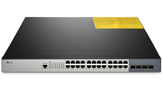
With the development of technology, network switch grows not only in speed like the migration from gigabit Ethernet switch, to 10gb switch, 40gb switch and 100gb switch, but also in complexity to acquire more functions and meet complicated conditions. Layer 3 switch is equipped with advanced functions and is sometimes compared with a router by people. What are layer 3 switch and router? Can a layer 3 switch act as a router? This post will focus on this problem.
What Is Layer 3 Switch and How It Works?
The data switch is a layer 2 switching device that dynamically transmits packets according to the physical addresses (MAC addresses) of connected devices. Layer 3 switch, on the basis of the data switch, boasts additional routing decisions by inspecting the IP addresses. Layer 3 switches are thus able to segregate ports into separate virtual LANs (VLANs) and perform the routing between them. Additionally, this switch helps reduce the amount of broadcast traffic, simplify security management, and improve fault isolation.

What Is Router and How It Works?
A router works at layer 3 of the OSI Model (Network). It is a device usually located at gateways where networks meet, to connect various local networks and wide networks. It decides where to send packets by utilizing an IP Routing table. When an IP packet comes in, the router looks up the destination IP in the IP Routing table. If that destination IP is not found in the table, the router will drop the packet. The router can perform NAT to translate the private IP address to public address, which can get you into the Internet. So it is a common network device in household use.
Can a Layer 3 Switch be Used as a Router?
As a layer 3 switch possesses the routing function of a router, can we replace a router with it? Let’ s have a detailed view of their similarities and disparities.

Layer 3 Switch Vs Router: Similarity

Both layer 3 switch and router work at layer 3 of the network. Layer 3 switches technically have a lot in common with traditional routers. Both of them can support the same routing protocols, inspect incoming packets and make dynamic routing decisions based on the source and destination addresses inside. The switches can also be configured to support routing protocols such as RIP, OSPF, and EIGRP.

Layer 3 Switch Vs Router: Disparity

Internally, the hardware inside a layer 3 switch blends that of traditional switches and routers. As for packet forwarding, router transmits packet by a microprocessor-based software routing engine, while the switch performs switching through hardware. After routing the first data flow, the layer 3 switch will generate a mapping table of MAC addresses and IP addresses, so that the same data flow will directly pass through the layer 2 according to this table, thus eliminating network delay and improving the efficiency of packet forwarding. Externally, layer 3 switches do not offer the WAN-type ports as standard routers do, so they lack WAN functionality.
Router requires configurations before deployment due to the inbuilt operating system. On the contrary, the layer 3 switch is usually ready to go when acquired, and configurations are optional as you like.
From a software perspective, layer 3 switches are not capable of the extra services that routers typically provide, such as NAT and NetFlow.
Conclusion
All in all, it is not recommended to replace a router with layer 3 switch, but you can apply them in the same network at the same time. In addition, whether a layer 3 switch can supplant a router relies upon the switch model and what you expect from it. Some layer 3 switches are almost router substitutions, with a full scope of WAN, firewall, VoIP, and so on. However, those switches are costly, and most layer 3 switches just have Ethernet ports. In this way, a dedicated router is cost-effective than a layer 3 switch.

Friday, September 14, 2018

Bend Radius—How It Can Impact Your Cable Performance?

Why should fiber optic cable not be tightly bent? Are fiber optic cable fragile? These issues are what users care about when deploying fiber patch cables. Usually, fiber optic cable is made from two bend sensitive materials: plastic or glass. It is broken easily when kinked or bent too tightly to exceed the minimum bend radius of cable. Then which factor will influence bend radius? How to choose cables according to it? This blog will provide some hints.

Why Bend Radius Is Important?

When you deploy the fiber optic cable, it is inevitable to flex, pull and bend it due to the practical conditions. However, it is the bend radius that determines how much you can bend a cable. It represents as the safe value that can prevent your cable from damaging or degrading its performance. If a cable is bent beyond its allowed radius, it will generate crosstalk or interference in data transmission, or even shorten its life. That’s why it’s important to know the bend radius of the cables, especially the minimum bend radius,which is the smallest allowed radius the cable can be bent around without signal loss or impairment.

Factors Impact Bend Radius of Cable

The bend radius may differ from cables. The fact is the smaller the minimum bend radius, the more flexible the cable. Here list some factors that may affect this radius of cable.
  • Outer Jacket Thickness
The thickness of the outer jacket of a fiber patch cable intended for bending will influence the potential minimum curve radius. Generally speaking, if the outer jacket is thick, the fiber patch cable will have a smaller bend radius. This can be translated by the fact that when the cable is bent, the stretching force makes the outer jacket thinner and even broken. Therefore, if the outer jacket is thin itself, the external tension may deform of break the fragile cable.
  • Material Ductility
Cables are manufactured by different materials, and this will affect the radius of the bend. Ductility refers to the flexibility of material under tensile stress or stretching force. If you would like to obtain small curve radius, you should choose cables made of highly ductile materials like copper. An alternative such as glass is more brittle than flexible.
  • Core Diameter
The large core diameter determines the small bend radius. Simply put, the single mode fiber has a smaller diameter than multimode fiber, and the single mode fiber cable bears less weight or bending than multimode fiber cable. That’s why the bending radius of single mode fiber optic cable is larger than the multimode fiber optic cable.

How to Choose Fiber Optic Cables based on Bend Radius?

Generally, the multimode fiber optic cable is recommended if the bend radius is the only consideration. And another option is BIF fiber cable. BIF means the bend insensitive fiber which enables tight curve radius when cables are bent or twisted. FS adopts it in producing both multimode and single mode fiber cables to endow them much smaller bend radii than ever before. It realizes more convenience in cable management, as well as less signal loss and less cable damaging. Here is a bend radius chart of BIF fiber optic cable.
Fiber Cable Type
Minimum Bend Radius
OM3/OM4 MTP BIF
7.5mm
Single Mode OS2 MTP BIF
10mm
Uniboot OS2 LC BIF
10mm
Uniboot OM3/OM4 LC BIF
7.5mm

Conclusion

To sum up, the bend radius of cables is paramount for fiber patch cable installations. Factors which influence the minimum radius of fiber optic cable include the outer jacket thickness, material ductility and core diameter. To protect the integrity and performance of cable, we shall not bend the cable beyond its allowed radius.

Friday, September 7, 2018

Connect Optical Transceivers of Different Brands, Fibers or Wavelengths

Optical transceivers usually work coordinately on a pair of network switches. As switch is responsible for directing the flow of data, optical transceiver works for transforming light to data or the opposite. Then how do two transceiver modules work with each other? Can I connect two optical transceivers of different brands, fiber types or wavelengths? You can find answers here.
How Do Two Optical Transceiver Talk to Each Other?
It is known to all that the fiber optic transceiver contains a transmitter and a receiver in the same component. These are arranged in parallel so that they can operate independently from each other. When working on two switches in the same network, the transmitter on one optical transceiver takes an electrical input and converts it to an optical output from a laser diode or LED. The light from the transmitter is coupled into the fiber with a connector and is transmitted through the fiber optic cable plant. The light from the end of the fiber is coupled to a receiver on the other transceiver where a detector converts the light into an electrical signal which is then conditioned properly for use by the receiving equipment.

Fig1. How optical transceiver works
Can I Connect Two Optical Transceivers of Different Brands, Fibers or Wavelengths?
When people are under-budgeted or in urgent need of original optical transceivers that are out of stock, they may turn to other or third-party transceivers. But how to make different transceivers work coordinately without link failure? Is it possible to connect two optical transceivers of different brands, fibers or wavelengths?

Optical Transceiver of Different Brands

As is known to all, fiber optic transceivers are manufactured with a lot of standards and protocols. If the SFP types are of the same protocol at each end, for example: both sides with SX, LX or whatever is currently in use, you can build the link between them. Please note that only the identical protocol is far more enough.
If the network switch comes from different vendors and optical transceivers with different protocols, you will get a dead link between network switch and the transceiver, thus the whole network fails. Make sure the transceiver and the switch at both ends are compatible with each other. However, as the transceiver compatibility is introduced to the optic field, many optical transceivers are now produced to be compatible with other brands. FS almost has no transceiver compatibility issues with other brand switches as all the optical transceivers have been tested to ensure its compatibility before shipping.

Optical Transceiver with Different Fiber Types

Common sense says a multimode sfp cannot work well with a single mode sfp, as the single mode fiber features a narrow core, allowing only a single mode of light to propagate while the multimode fiber has a wider core enabling multiple modes of light to propagate.
Well, as the network evolves, it is unavoidable to use single mode devices on the existing multimode fiber cables, which forces the birth of the mode conditioning cable used for single mode to multimode conversion. It is generally a duplex multimode cable that has a small length of single mode fiber at the start of the transmission length. As for optical transceiver with single mode fiber, connect the single mode connector of the cable into the transmit bore of the transceiver, and multimode connectors of the cable into the receive bore of the transceiver with all other connections going as normal.

Fig.2 Optical transceiver works with mode conditioning cable

Optical Transceiver on Different Wavelengths

A given transceiver generally supports a specific wavelength for both transmitting and receiving. It is vital the wavelength of the fiber optic transceivers (850nm, 1310nm, 1550nm) matches on each end, as a 1310nm sfp transceiver will not talk to a 850nm sfp transceiver. Data transmission implies that data is sent from one end to the other. The SFP transceiver on one end converts electrical signals into optical signals. A built-in laser transmits light through the fiber to the other side. Here, an optical diode converts the light back into an electrical signal. To guarantee that the SFP at the other end is capable of doing this, the SFPs at both ends should support the same wavelength.

Fig.3 Different wavelengths of optical transceiver
Conclusion
To make sure your optical transceivers work smoothly with each other, be careful about their protocols, wavelengths and fiber types in case of link failure. FS provides a great range of fiber optic transceivers with no transceiver compatibility problem and transceiver prices are very competitive.

Friday, August 31, 2018

DWDM Vs. OTN: What’s the Difference?

As we slip further in the internet era, the internet boom pushed service providers to find a method to increase the capacity on their network in the most economical way. Therefore, two technology come into our sight: DWDM vs. OTN, the technologies that can expand existing bandwidth. To learn more about them and the difference between OTN and DWDM, this article may be of some help.

DWDM Vs. OTN: DWDM Basics

What is DWDM? DWDM stands for dense wavelength division multiplexing. It is a technology to send multiple strands of data through a single network link. In the transmitting end, there is an optical multiplexer converging two or more optical signals at different wavelengths. Whereas in the receiving end, an optical demultiplexer is used to separate the signals, and in this process it is unavoidable to cause signal loss which, however, can be mitigated by the optical amplifier. DWDM connections can therefore be used for transmitting data over long distances as it can increase bandwidth over existing fiber networks.

DWDM Vs. OTN: OTN

OTN stands for optical transport network which provides a network-wide framework that adds SONET/SDH-like features like performance monitoring, fault detection, communication channels, and multiplexing hierarchy to WDM equipment. It works at Layer 1 to gather various tasks into the tunnel of WDM technology, increasing the transmission distance and capacity of fiber optics. It means that OTN frame structure combines the flexibility of SDH/SONET technology with the bandwidth expandability of DWDM, thus it can provide functionality of transport, multiplexing, routing, management, supervision, and survivability of optical channels carrying client signals.
The optical transport network is designed to deliver a transparent framework to efficiently carry diverse traffic types, which can decrease ACPEX/OPEX in networks and at the same time address dramatic shifts in traffic types. All in all, the charming of the OTN can be translated into two words: transparency and manageability.

Difference Between DWDM and OTN

DWDM is a point-to-point system while OTN, composed of optical cross-connector (OXC) and optical add/drop multiplexer (OADM), possesses functions like optical cross-ability and wavelength conversion. The OTN grows on the basis of DWDM technology with the aim of optimizing the existing resources of transportation network. In addition to providing large capacities of DWDM transmission, OTN permits the switching of different DWDM channels according to the needs of traffic.
In addition, as it has been proven that it is possible to tap a fiber optic cable and extract data streams, people have paid much more attention to data security over DWDM links. In contrast, OTN-channelized links and effective partitioning of traffic onto dedicated circuits bring a high level of privacy and security, preventing hackers who sneak in some section of the network from intercepting data or gaining access to other areas.
We can say that OTN network excels DWDM networks in its enhanced OAM, security and networking capabilities for wavelengths and standard multiplexing hierarchy and end-to-end optical transport transparency of customer traffic.

Conclusion

DWDM vs. OTN, the topic being addressed in this article, makes sense for those who want to better utilize them and is worthy of being explored further. Though there are indeed differences between OTN and DWDM, the two technologies are irreplaceable and have become the key point in the telecommunications infrastructure for regional networks as the allows bandwidth over existing networks. FS focuses on providing customers the best technical support, engineering cost effective and scalable solutions for metro and long-haul DWDM network. For more details, visit this website.

Thursday, August 23, 2018

NAT: Why Do We Need It?

NAT, which is critical to the IPv4 networks we still use today, has been hotly debated as the IPv6 grows with more addresses. However, since the IPv6 is not full-fledged, the existence of NAT still makes sense. Here I will introduce NAT definition and figure how NAT works and why we need it.

What Is NAT?

NAT, known as network address translation, is the method adopted by a firewall or router to assign the public addresses to the devices work in the a private network.
It translates the private IPv4 addresses we use in our internal networks into public IPv4 addresses that can be routed over the internet. As we all know, the private addresses may be occupied by connected local service—computers, game consoles, phones, fiber switches etc. to communicate with the modem/router and other devices on the same network. However, the home network connection uses a single public IP address to access the internet. Given this, NAT is responsible for translating the IP address of every device connected to a router into a public IP address at the gateway. Then those devices can connect to the internet.

NAT: Why We Need?

Assume that you have 3 PCs, a gigabit Ethernet switch which connects 6 PCs, a 10 gigabit switch connecting 6PCs and one smart phone, two ipads and all of them need to work at the same time, then you need to get each of them an IP address accessible to the Internet. But due to a lack of IPv4 IP address space, it is hard to handle the massive number of devices we use every day. Well, the network address translation, proposed in 1994, has become a popular and necessary tool in the face of IPv4 address exhaustion by representing all internal devices as a whole with a same public address available. Together with its extension named port address translation, the network address translation can conserve IP addresses.
Safety, another issue we may concern when accessing the external internet, can partly be addressed by network address translation which servers as a strict controller of accessing to resources on both sides on the firewall. The hackers from outside cannot directly attack the internal network while the internal information cannot access the outside world casually.

How Does NAT Work

A router carrying NAT consists of pairs of local IP addresses and globally unique addresses, by translating the local IP addresses to global address for outgoing traffic and vice versa for incoming traffic. All these are done by rewriting the headers of data packets so that they have the correct IP address to reach the proper destination.
There are generally two types of NAT: dynamic and static.
In dynamic NAT, we map inside local addresses in internal network to global addresses so that they can access resources on the internet. The router responds to the hosts who want to access the internet with an available public IPv4 address so that they can access the internet.
In static NAT, we usually map an internal local address to a global address so that hosts on public networks can access a device in the internal network.

Conclusion

In a word, before the full transition of IPv6, NAT can guarantee the smooth internet surfing no matter how many devices you’ve got. Knowing what it is and how it works with network address will help you establish a clear understanding of it so that you can make good use if it.

Sunday, August 19, 2018

SDN vs. OpenFlow vs. OpenStack: What’s the Difference?

As the network grows, the network equipment producers flourish, bringing many different exclusive products into the market. How to manage or operate so many equipment as the different vendors own diversified CLI and web interface to debug and configure. It’s time to put forward some new technologies, SDN vs. OpenFlow vs. OpenStack to tackle this problem.
SDN VS OpenFlow vs. OpenStack: What Are They?

SDN-Software Defined Network

Software-defined networking (SDN) technology is a new way to cloud computing.To improve network monitoring and performance, SDN is designed to enhance network management and promote programmatically network configuration efficiently. It centralizes network intelligence in one network component by decoupling the forwarding process of network packets (data plane) and the routing process (control plane). SDN is mainly composed by application layer which provides application and service, control layer responsible for unified management and control, and forwarding layer that offers hardware equipment like fiber switches, Gigabit Ethernet switches and routers to forward data. The following table illustrates the advantage of SDN against traditional network.
Software-defined Network vs. Traditional Network

OpenFlow: the Enabler of SDN

To turn the concept of SND into practical implementation, we need to put into place some protocols, among which OpenFlow is the most desirable one. So what is OpenFlow?
OpenFlow is a communications protocol that empowers a network switch or router to access the forwarding plane over the network. Also it can serve as a specification of the logical structure of the network switch functions. We know that each switch vendors may have their own proprietary interfaces and scripting languages, and this protocol enables them to work coordinately while avoid exposing their technology secret inside switches to the public.

OpenStack

OpenStack is an open source cloud computing management platform project that combines several major components to accomplish specific tasks. Its existence confronts the AWS of Amazon, as it allows all participators to access the source code and share some ideas, if they want to. It is convenient and reliable with strong compatibility and adaptability, gaining support from many vendors.

SDN vs. OpenFlow vs. OpenStack: What’s the Difference?

SDN vs. OpenFlow

SDN and OpenFlow are prone to be confused and misunderstood. Take a look at SDN vs. OpenFlow, the two are indeed interconnected. First of all, as an open protocol, OpenFlow underpins the various SDN controller solutions. The complete SDN solution is taking SDN controller as the core, backed by OpenFlow switches and NFV to offer bountiful SDN app for a new smart, dynamic, open, custom network.

OpenFlow vs. OpenStack

OpenFlow, since its release, has gained achievements in hardware and software support. CISCO, Juniper, Toroki and pronto have all launched network equipment like 10gbe switch, router, and wireless access point which support OpenFlow. In contrast, OpenStack covers many aspects like network, virtualization, operation system, and server. It is an ongoing cloud computing platform.

SDN vs. OpenStack

Network orchestration OpenStack copes with the component organization of a particular group of assets, from open source or closed implementations, thus we can say that it can be considered how a software-defined network is deployed. While SDN control serves like the commander of organizers and deals with maintaining consistent (as far as is feasible) policy across multiple groups of assets, so we deem it much like the "why."
Conclusion
SDN vs. OpenFlow vs. OpenStack, the three terms that are of far-reaching significance, attract more attention from the public. This article may provide you with some help to know them at the very first step. Till now, the networking technologies are still advancing, knowing what they are at present doesn’t mean the truly master of it. There is still plenty of room left to be explored
.

Sunday, July 22, 2018

What Is Redundant Link between Switches?

We know that if any chain in the network fails, the operation may break down. Facing this problem, we’ve introduced the stackable switches and together with it is the concept of redundant links. When stacking switches, except the shortest link between switch and the main frame computer, we also prepare other links in case of the break down of the major link. The other links are redundant links between switches.

Introduction of Redundant Link

In order to maintain the stability of the network, composed of multiple switches, some backup connections are usually used to improve the robustness and stability of the network. The backup connection here is also called a backup link or a redundant link. Redundant links in a switches are accomplished through the use of multiple switches or multiple links between switches.
In an enterprise network, a link is redundant if its presence or absence does not affect the nature of the mechanism. That is, even if we remove that link, the mechanism will behave in the same manner.

Pros and Cons of Redundant Link

Pros
The redundancy in networks can improve its reliability. Our intention is that if one device fails, another can automatically take over. By adding a little bit of complexity, we try to reduce the probability that a failure in switch will take the whole network down. Spanning Tree Protocol,the redundancy protocols, can be implemented on any topology or mesh. The Cellular Redundancy provides alternative to running a physical line for redundancy. In addition, with Parallel Redundancy Protocol, we can achieve zero packet loss, “0ms” recovery. And it can be added to any existing network.
Cons
But you cannot have both complexity and reliability at the same time. The more complex something is, the harder it is to maintain, the greater the chance of human error, and the greater the chance of a software bug causing a new failure mode.
The switches between the backup links are often connected to each other to form a loop. The loops can be redundant to a certain extent. The redundant backup of the links can bring robustness, stability and reliability to the network. However, the backup link also causes loops in the network. The loop problem is the most serious problem faced by the backup link. The loop between the switches will cause new network problems: broadcast storm, loops and duplicate frames.

Tips

To make fully use of redundant links, we can minimize the complexity. Select two identical switches as the core switches. If you need gigabit Ethernet switch, for example, you can select two 10 gbe switches that run the same software and have the same connections. We can also introduce the Spanning Tree Protocol (STP) which was developed as a Layer 2 loop-avoidance mechanism for redundant links in a switched network. With STP, there will be only one logical path between all destinations on the network and redundant links that could cause a loop are intentionally blocked.

Conclusion

Redundant links are useful to a great extent. That’s why so many people now choose stackable switches rather than standalone ones to maintain the efficient network operation. Stackable switches are now our star products and focal point. We would like to introduce our high quality fiber switch to every people in need of reliable network performance.