Sunday, July 8, 2018

Patch Panel Cabling—the Right Choice

What Is a Patch Panel?

The patch panel is a device that integrates both cable management and termination functions. The patch panel cabling is conducive to the structured cabling as the cables are put orderly on the patch panel. As the interface between multiple optical fibers and optical equipment, it serves as a termination unit that helps networking and fiber distribution from wiring closet to various terminal applications.
Lying on the front of it are an array of ports where we insert the cables. The ports in the back will lead to a server, switch, or another type of device. Each port in the front will have a cable coming from a PC, phone, fax, or any other device that needs to be networked together. Each port on the patch panel labeled with a number will connect via an Ethernet cable punch down on the back, through the wall, cross space or added to another location in the house.

Benefits of Patch Panel Cabling

It lets you use the proper type of cable in the proper place. Other than the point-to-point cabling, the patch panel contributes to a structured cabling, representing you a professional and neat look. In a large home or office with lots of connections, patch panels make quick work of re-configuring networks by enabling operators to identify where the cable is coming from and going to. By managing varying port densities and speeds in a single high-density patch panel, you save valuable rack space, helping to lower data center costs. A single patch panel can manage as many as (168) 10Gb ports.

Patch Panel Recommendations

We all know that the fiber transmits data faster than copper does. But the role of patch panels is to direct signal traffic rather than send the signal at a certain speed. Both copper and fiber panels are governed by the same TIA/EIA standards(the highest level of criteria that products must perform to) required to produce speed and signal performance for the rest of the cabling network. Patch panels must coerce data into performing up to the standards.
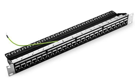
The 24 ports Cat5e shielded feed-through patch panel, a star product in FS.COM, can be mounted in to 1U racks. The shielded patch panel can minimize the crosstalk between cables, ensuring the smooth transferring of signals. It features with number coding, removable rear cable manager and rear cable management bar.

1U 19" high-density fiber patch panel offered by FS.COM can hold up to 48 fibers with 24 ports. High quality steel adapter panel is suitable for 1U 19" frame rack mount or cabinet, designed for backbone-to-backbone and backbone-to-horizontal fiber cabling. It is fully loaded with fiber couplers to save much cost.

Conclusion

A patch panel allows you great flexibility to move, add and change cables. It gives you the neat look and a simple way to manage and configure and reconfigure your network. If coordinated with a cable manager, the patch panels will do better in cable management since the cable manager has both horizontal and vertical options while the patch panel is only designed in horizontal type at present. It can be easily installed into the wall mount enclosure and rack mount enclosure. What’s more, the whole rack will be much nicer and the networks will work orderly. Remember that 30% space in the cable managers should be left for future growth.

Friday, June 29, 2018

Things You Should Know About Patch Panel Cabinet

Cables are in the right position. Patch panels are terminated. All slack cables are put orderly in the cable manager. Let’s see what is missing? Well, where should the patch panels and cable managers be? Just lying on the ground? If indeed, the previous efforts for cable management is wasted. Just with a cabinet or a server rack, you can solve the problem. There are thousands of cabinet for different use, but here we refer to the network patch panel cabinet.

Network Patch Panel Cabinets Introduction

We have wall mount cabinets that has the maximum height of 12U and the normal cabinets standing on the ground that can reach to 45U. Unlike the open frame rack which consists of two or four mounting rails (called posts) without sides or doors, the wall mount cabinet is enclosed by SPCC cold roll steel panels and a glass front door to make its inside visible. The side panels can be removed easily for quick access to equipment and cabling. On the top of the patch panel cabinet, there is a cooling vent to ensure smooth airflow, preventing over-heat in it to further protect equipment. It is designed to house the 19-inch standard that is consistent with most patch panels in FS.COM or non-standard network equipment as well as network accessories. The wall mount cabinet is shipped fully assembled and is ready to mount to the wall.
As for the floor-standing network patch panel cabinet, the ventilation can be naturally achieved as the front door is perforated and the top panel is attached with brush guards to prevent over-heating. It has four casters helping with its move. Top, bottom and back cable access openings provide convenient and multiple cable routing choices to and from the patch panel cabinet.

Layout Inside the Patch Panel Cabinet

We all know that all patch panel are put in the cabinet, be it fiber optic patch panel or Ethernet patch panel. However, the question is whether it is on the front side or back and with the jacks facing in or out?
In most cases, we will start with an empty patch panel cabinet, and then install the devices on its front rails from top to the bottle. First comes the cable manager 1, then follows the patch panel 1, cable manager 2, switch 1, cable manager 3 and switch 2, with all the connectors on the back side of the patch panel cabinet. All gadgets ready, we can go on with the cabling. The patch panel here can be fiber or copper patch panel.

The importance of a patch panel cabinet is no less than that of a tiny screw or a nail. And great attention should be focused on it since the patch panel cabinet can support the other device and prevent them from external damages. A solid and durable patch panel cabinet is necessary, which is actually what FS.COM aims at. There are 9U and 12U, two choices for you to meet different application. To ensure the best performance, 1 bag of nuts and bolts, 1 T-Shaped Lever will be offered for free. And there are so many surprises in the patch panel cabinet that I want to leave it for you to find yourselves. You will find them when installing and using the patch panel cabinet from FS.COM.

Wednesday, June 27, 2018

Collections of Cable Manager for Rack

Introduction

Long before the born of cable manager, the mess cable management with cables hanging here and there has been a cloud over the data center and server room. How can you realize each smooth and convenient operation on your network application with network cables looking like messy spaghetti? Here we list four common cable managers to simplify your cabling and minimize the trouble during operation.

Different Types of Cable Manager

The following cable managers which you may have heard of or seen before are the most popular types in the market. Each has its unique design and characteristics.
Cable Manager with Brush Strip
The panel is designed to be mounted on any 19in EIA style rack or cabinet and features built-in brush that allows passage of up to 25 cables while blocking airflow, ensuring optimal thermal performance. The steel construction provides durability, resists corrosion, and keeps your rack looking smooth and professional.

Cable Manager with Finger Duct
The FS.COM finger duct horizontal cable manager is designed with flexible fingers, rear pass-through holes and a removable cover. The soft and durable finger ducts offer proper bend radius and flexible operation of cable management, keeping the structured cabling system unhurt and totally functional.

Cable Manager with D-rings
The name of D-rings cable manager originates from the fact that five metal D-rings stand vertically on the cable management panel in a good order. Horizontal cable management panels with D Rings are built with steel for strength and durability. Easily route large amounts of cable through robust rings. The D-Rings organize patch cords and maintain a required bend radius. They are available in sizes of 1U and 2U.

Cable Manager with Bend Radius Finger
This cable manager is equipped with six or five bend radius control fingers, consuming much fewer material. The total length of it is 222mm. Light in weight, this type of bracket can be installed in specific areas of the rack, rather than along its entire height. Moreover, it can be stacked to reach any height(U), so it can be an alternative of higher vertical cable management.

How to Apply Cable Manager

Cable managers often come together with patch panel to make the patch cables in the front side of patch panel more orderly. Generally, in a server rack, the cable can’t either be put solely on cable manager since it is incompetent for termination, or be applied to just a patch panel due to its imperfect cable management. Therefore, to realize the perfect cable management, we need to deploy this couple at the same time. The cables going out from the patch panel have already gone through the management process, but it should go to the next cable manager installed above or below the patch panel, so that the whole cable management can be finished. Additionally, some people will need the further step to bring the cables that are from horizontal cable management to the vertical cable managers standing at the both sides of the cabinet.

Conclusion

Never look down upon cable management, otherwise the cables haphazardly thrown around will be your nightmare. In case it damages the wires and cause other hazards, now it’s time to arrange your cables properly. FS.COM has many kinds of cable managers to help make your life neater!

Friday, June 22, 2018

Ethernet Patch Panel Still Shining on the Market

The patch panel, a significant element in cabling design, has many ports on it. Through these ports, the cables are located elsewhere in your building. Patch panel at present has fiber and copper patch panel(also known as Ethernet patch panel), two choices for us. As we all know, a single fiber optic patch panel is not available to all kinds of fiber cables. The same is to copper patch panels which are classified as Cat5e patch panel, Cat6 patch panel and so on.

CAT5e Ethernet Patch Panel VS. CAT6 Ethernet Patch Panel

Both as the copper patch panel, Cat5e patch panel and Cat6 patch panel don’t have many differences, except that Cat5e patch panel usually works with Cat5e, while Cat6 patch panel can work with both the corresponding Cat6 cable and any earlier generation of Cat cable. The patch panels themselves don’t have many practical differences. However, there is indeed a difference in the wire gauge specified between Cat5e and Cat6. The cat6 wire is thicker in that Cat6 usually has 23 AWG copper conductors compared to only 24 AWG in Cat5e cable.
The 24 port patch panel used for different cables are both welcomed by customers. 24 port cat6 patch panel offered by FS.COM acquires acknowledgments from many customers and IT experts. With easy installation and top-quality performance, the high quality patch panel is designed for Fast Ethernet applications. 24-port Cat5e patch panel is the most popular in the market, which has punch down and feed-through patch panel for customer choice. And when applying patch panels to special environments, for example nearby motors, generators, air conditioners, and even office mainstays such as fluorescent lights and printers, you should carefully consider between shielded and unshielded patch panels.

Shielded Ethernet Patch Panel VS. Unshieleded Ethernet Patch Panel

Shielded and unshielded patch panels are required to match with the shielded and unshielded copper cable applications. Shielded patch panels are designed for high EMI (Electro Magnetic Interference) environments. If the application environments have special requirements for crosstalk and EMI functions, especially when the copper cable runs near power cables then you should choose to use shielded Ethernet cables with shielded patch panels. However, someone may wonder whether they can use unshielded patch panel for shielded cable. To be honest, it depends on the environment in which your cable will run through. If the place has no high power electrical wires, you can go with unshielded patch panel. On the flip side, if you are in a noisy environment like using arc welders or near high power radio transmitters, then you’d better select the shielded one. FS.COM shielded and unshielded patch panels can meet not only 1G network speed, but also 10G network.
For both shielded and unshielded applications, you can find what you need at FS.COM. The port number marked on the FS.COM patch panel provides easy cable identification. The cable manager on the rear side is removable, providing efficient and organized cabling.

Conclusion

CAT5e and CAT6 cables are the most popular Ethernet cables on the market. To create a nicely organized cabling environment, choosing the right patch panel is essential. Sometimes Cat5e, Cat6 or other Ethernet cables need to be managed in a single panel, in this type of situation, the blank keystone patch panels can support mixed cabling with installation of different rj45 insert modules. In addition, you can customize your patch panel according to your specific applications. FS.COM provides a large variety of patch panels and Ethernet cable and also presents a selection of cable managers to help you create your ideal cabling network. For more details, please visit our website.

Tuesday, June 19, 2018

D-Ring Cable Manager for Horizontal Cable Management

The horizontal cable management solutions are springing up one after another as is expected. After the the explanation of versatile fiber optic patch panel, punch down patch panel, upgraded fiber enclosure, and various cable managers such as brush strip cable manager, finger duct cable manager, horizontal and vertical manager, we now focus our eyes on the new horizontal cable manager with D-rings.

The Structure of D-ring Horizontal Cable Management Tool

The name “D-ring” stems from its design that a ring goes in “D” frame. The five metal D-rings stand vertically on the cable management panel in a good order. Without complicated design, it won’t add unnecessary trouble in the cabling procedure or additional energy for you to identify each gadgets. For 1U cable management, we have 1U horizontal cable management with D-rings, and 2U horizontal cable manager with D-rings for 2U cable management.

The Advantage of D-ring Horizontal Cable Management Tool

Why is the D-ring horizontal cable manager standing out among all those cable managers? Why you want choose it? Look here.
For those who want neat and clean cable management, it perfectly caters to their need as it uses a D-ring method of cable management to run cables vertically along the side of your rack, neatly guiding them between equipment that’s mounted at different heights. This provides a tidy and well-organized way to run cables from devices mounted toward the bottom of your rack to other devices mounted near the top, without leaving a mess of cables hanging in between.
For those who long for easy installation and effortless maintenance, this D-ring cable manager can satisfy them because having neatly organized and routed cables not only improves the appearance and accessibility of your rack, it also makes it easier for you to install, access and maintain rack components. As a consequence, we can see that it improves the appearance and accessibility of your rack. That’s why we want to have it.

How to Arrange Horizontal Cable Management with D-ring Cable Manager

The user-friendly design makes it easy to use by customers and even novices. With screws and installing tools, you can attach this device onto server rack or cabinet. In the video, the cable managers are sitting below the switch. When the fiber cables on the switch are all on their position, we can now come to the cable management step. The first 4 fiber cables pass through the first ring and go through the second ring together with another 4 cables and so on. A single horizontal cable manager with D-rings can manage up to 70 patch cables. Here if you use cable ties to strap the cable, it will be the icing on the cake.
If you keep wondering where your power cords and video cables go in your 24 port patch panel, then our horizontal cable management panel with metal D-rings to provide stability so each cable can make a clean entry and exit. Make your patch panel look organized and professional. FS.COM horizontal cable management solutions provide data center managers and IT professionals with a variety of options.

Thursday, May 18, 2017

How to Save Cost for 500Gbps Metro Network Over Long Distance?

Increasing bandwidth has always been the most important task of telecom engineers. Through decades of research and engineering effort, 40Gbps and 100Gbps solutions have been used for network applications. But 40G and 100G transceivers can’t support too much long distance (QSFP-40G-ER4 for 40 km, QSFP-100G-LR4 for 10 km). How to extend the 500Gbps link to thousands of kilometers in Metro network within limited budget?
Save Fiber Cost–500Gbps Over Single Fiber Cable
Fiber cable cost takes a certain percentage in the whole network budget. Point to point connection needs many cables, while WDM technology take well care of this issue. In a metro network, usually multiple 10Gbps signals are transmitted by the use of DWDM Mux/Demux over a single fiber cable, which can save lots of money on multiple fiber cables and cable management issues. Then how to save cost to transmit 500Gbps signals over single fiber cable?
It sounds unbelievable. But we have the cost-effective solution. As we know, it will cost too much to replace all the current network system for upgrading to higher data rate. To save cost for increasing bandwidth, some producers add an extra port on DWDM Mux/Demux and that is 1310nm or 1550nm port. This port supports 1310nm or 1550nm transceiver. With such port, you can add 1G/10G/40G/100G to the existing DWDM network. For instance, we use 40-channel C21-C60 dual fiber DWDM Mux/Demux with 1310nm port and 1310nm band port for 1G/10G/40G/100G “grey” light. Plug 10G DWDM SFP+ transceivers into 40 channels, the overload is 400Gbps. Once plugging a 1310 40G QSFP+ LR4/ER4, then the total link reach up to 440G (400G + 40G). If install a 100G QSFP28 LR4 transceiver into 1310 port, the whole transport will be 500Gbps (400G + 100G). See this solution realize the goal of saving cost to run such huge network load over a single fiber.

Extend 500G Transmission Distance
Since 500G signals can be transmitted over a single fiber cable, we have another issue to be solved. 500G transmission distance is needed far more than few kilometers in real life, maybe thousand of kilometers. How to extend the transmission distance?
According to IEEE standard, LR4 and ER4 transceivers can support the reach of 10 km and 40 km in the in ideal conditions, not considering fiber loss or connector loss. To extend 500Gpbs transmission distance, we need SOA (Semiconductor Optical Amplifier) and EDFA (Erbium Doped Fiber Amplifier). Add an SOA to support 40G/100GBASE-LR4 transceiver (over 1310 nm). The SOA is used to amplify incoming (Rx) signal on the receiving side of the link. So that the distances can reach up to 60 km. In 10Gbps DWDM networks, the signal transmission distance can be extended to hundreds of kilometers by the use of and EDFA (Erbium Doped Fiber Amplifier).

Recommended DWDM Solutions for 500Gbps Metro Network
ID#FS Part NumberDescription
3588740MDD-1RU-A1-FSDWDM40 Ch 1RU Duplex DWDM MUX DEMUX C21 to C60 with 1310nm Port and Monitor Port
14491DWDM-SFP10G-4010GBASE 100GHz DWDM SFP+ 40km, LC Duplex Interface, C21 to C60
31533DWDM-SFP10G-8010GBASE 100GHz DWDM SFP+ 80km, LC Duplex Interface, C21 to C60
14599DWDM-XFP10G-4010GBASE 100GHz DWDM XFP 40km, LC Duplex Interface, C21 to C60
14650DWDM-XFP10G-8010GBASE 100GHz DWDM XFP 80km, LC Duplex Interface, C21 to C60
35208QSFP-LR4-40G40G QSFP+ LR4 1310nm 10km, LC Duplex Interface
35210QSFP-ER4-40G40G QSFP+ ER4 1310nm 40km, LC Duplex Interface
35014CFP2-LR4-100G100G CFP2 LR4 1310nm 10km, LC Duplex Interface
35192FS-SOA-G1010dB Gain 1310nm Semiconductor Optical Amplifier
31366EDFA-BAO2220dBm Output C-band 40 Channels 26dB Gain Booster EDFA
Summary
DWDM technology is very necessary to extend Metro Network reach. In this 500Gpbs Metro network, I have introduced very detailed cost-effective solutions. Remember all the indispensable DWDM equipment such as DWDM transceivers, DWDM Mux/Demux, EDFA, etc. For more information, please visit the site about FS.COM Long Haul DWDM Network Solution.
Originally published at http://www.fiber-optic-equipment.com

Thursday, May 4, 2017

Which 40G QSFP+ Transceivers Can Be Used for 4x10G?

Since the overwhelming growth in data traffic, many data centers are loaded with 10G and 40G based Ethernet switches for 10G to 40G migration. 40G switches allow the configuration of 40G port to act as one port or break out into four individual ports. To get easy 10G/40G migration, we should better select 40G QSFP+ transceivers which can break out as 4x10G connectivity. Among so many versions of 40G QSFP+ transceivers including QSFP-40G-SR4, QSFP-40-CSR4, QSFP-40G-LR4, QSFP-40G-ER4, etc., which 40G QSFP+ transceiver can be used for 4x10G?
QSFP-40G-SR4/CSR4 for 4x10G
40G short distance multimode transceivers are interfaced with 12-fiber MTP/MPO, such as 40G SR4, CSR4. To know why these 40G QSFP+ modules can be used for 4x10G, let’s see how QSFP-40G-SR4 work? First, 4 electrical input signals of 10G converted into parallel optical signals are sent from the transmitter over 4 parallel fiber strands. Then the parallel optical signals are converted into parallel electrical signals by the use of a photo detector array and transmitted to the receiver over another 4 parallel fiber strands. QSFP-40G-SR4 needs 8 fibers to transmit and receive signals. QSFP-40G-SR4 transceivers are interfaced with 12-fiber MTP/MPO. Therefore, QSFP-40G-SR4 and QSFP-40G-CSR4 transceivers can be easily broken down to 4x10G connections. Each 10G signal lane of QSFP-40G-SR4 is compliant to IEEE 10GBASE-SR specifications. And this 10G/40G connection can be achieved by using an MTP-LC harness cable or MTP cable and MTP-LC breakout patch panel to connect the QSFP-40G-SR4 and four 10GBASE-SR modules.


Can QSFP-40G-LR4/ER4 Be Used for 4x10G?
QSFP-40G-LR4 transceivers apply CWDM (Coarse Wavelength Division Multiplexing) technology. From the transmitter side, 4 input electrical signals of 10G are converted into 4 CWDM optical signals by a driven 4-wavelength distributed feedback (DFB) laser array. Then 4 CWDM signals are multiplexed to a singlemode fiber for 40G optical signal transmission. On the receiver side, the receiver accepts 40G CWDM optical signals input and demultiplexes them into 4 individual 10G optical data streams with different wavelengths. Multiplexing and demultiplexing of the four wavelengths are managed in the device. The 40 Gigabit Ethernet signal is carried over four wavelengths on a pair of singlemode fibers. The duplex fibers are used for bi-directional transmission. QSFP-40G-LR4 and QSFP-40G-ER4 are interfaced with duplex LC connector. Therefore, we can’t split QSFP-40G-LR4 or QSFP-40G-ER4 to 4 individual duplex SMF fibers to route them to 4 separate 10G transceivers by simple optical rerouting.
But if you insist to split the 40G into four 10G streams using QSFP-40G-LR4 or QSFP-40G-ER4 modules, how to achieve that connection? Then you need a simple multiplexer/demultiplexer which split the four wavelengths on duplex fibers into 4x10G signal in four different fibers. With such equipment, the QSFP-40G-LR4 or QSFP-40G-ER4 outputs can be physically broken down from one duplex fiber into four duplex fibers so that each of the wavelengths is transmitted in four different fibers (As the following figure shows).

How About QSFP-40G-PLRL4?
From the above content, you may get an inclusion that multimode 40G QSFP+ transceivers can be directly used as 4x10G while singlemode 40G QSFP+ transceivers can’t. However, you ignore one singlemode transceiver QSFP-40G-PLRL4. This 40G QSFP+ transceiver connects with 12-fiber MTP/MPO patch cable though it’s designed for long distance transmission. Similar to QSFP-40G-SR4, QSFP-40G-PLRL4 also needs 8 fibers to transmit and receive signals. So you can easily get 10G/40G singlemode connection applying QSFP-40G-PLRL4.
Summary
Some data centers may face the issue of migration from 10G to 40G. Except the switch, you also need to know 40G QSFP+ transceivers well especially what kind of 40G QSFP+ transceivers can be used for 4x10G connectivity. In this article, you can see 40G QSFP+ transceivers with MTP/MPO interface can achieve that connection by simple optical routing. As to 40G QSFP+ transceivers with duplex LC interface, you need spare equipment for multiplexing/demultiplexing. For 40G to 4x10G solutions, you can find your desired one from FS.COM.
Originaly published at www.fiber-optic-equipment.com