The local area network (LAN) campus and building backbones as well as data center backbones are migrating to high cabled fiber counts to meet system bandwidth needs and provide the highest connectivity density. So manufacturers start to produce MPO/MTP high density cables. Then many network designers are turning to MPO/MTP trunk cable to get the highest connectivity density for an easy migration from 10G to 40/100G. To ensure reliable system performance as well as support ease of installation, maintenance and reconfiguration, MPO/MTP cables require unique polarity design. But how to maintain proper MPO/MTP polarity?
Optical fiber links typically require two fibers to make a complete circuit. Optical transceivers have a transmit side and receive side. In any installation, it is important to ensure that the optical transmitter at one end is connected to the optical receiver at the other. This matching of the transmit signal (Tx) to the receive equipment (Rx) at both ends of the fiber optic link is referred to as polarity. In traditional cabling systems, single fiber connectors such as LC, SC are used. So it’s easy to main the polarity as long as the A side of one connector pair matches to the B side of the other connector pair in any patch cord or permanent link. However, pre-terminated, high-density cabling systems based on MPO/MTP array connectivity require a new set of design rules and have their more complicated requirements for maintaining proper polarity. Before talking about maintaining MPO/MTP polarity method, we will first introduce MPO/MTP array connectors.
MPO/MTP Array Connectors
MPO/MTP array connectors terminate multiple fibers in a single high-density interface. 4-, 6-, 8-, 12-, 24-, 36- and 72-fiber connectors are available. But 12-fiber array connectors are the most common. MPO/MTP array connectors are employed in high-density permanent link installations and can be found in pre-terminated cassettes, trunk and hydra cable assemblies used extensively in data centers.
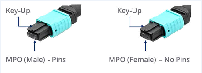
MPO/MTP array connectors are pin and socket connectors (as shown in the following picture), requiring a male side and a female side. Cassettes and hydra cable assemblies are typically manufactured with a Male (pinned) connector. Trunk cable assemblies typically support a Female (unpinned) connector. To ensure proper end-face orientation during mating process, connectors are keyed. When the key is at the bottom, it’s called key down. When the key is on the top, it’s called key up. Under the situation of key up, the fiber holes in the connector is numbered from left to right as P1, P2... There is a white dot on one side of the connector to identify where the P1 is.

Three Polarity Methods
The following will introduce three different methods to maintain polarity for systems using MPO/MTP optical connectivity. Defined by TIA/EIA-568-B.1-7, these methods include installation and polarity management practices, and provide guidance in the deployment of these types of fiber array links.
Method A
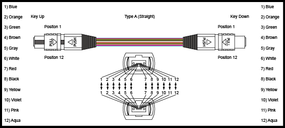
Method A employs Key Up to Key Down adapters to connect the array connectors. In this straight through configuration, Fiber 1 (P1) in the near end cassette mates to Fiber 1 (P1) in the trunk cable assembly. That is to say fibers at each end of the cable have the same position. Method A provides the simplest deployment for single-mode and multimode channels, and can easily support network extensions.

Method B
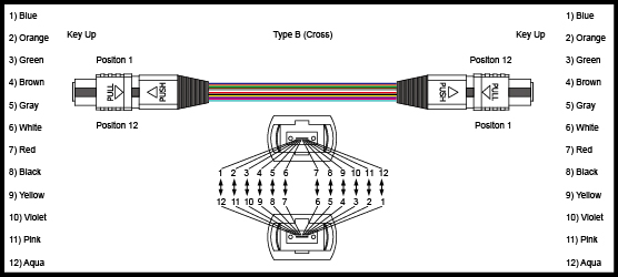
Method B uses Key Up to Key Up Adapters. The fiber circuit is completed by utilizing straight patch cords at the beginning and end of the link, and all of the array connectors are mated Key Up to Key Up. In this method, the fiber positions are reversed. Fiber 1 is mated with fiber 12, Fiber 2 mated with Fiber 11... To ensure proper transceiver operation with this configuration, one of the cassettes needs to be physically inverted internally so Fiber 12 is mated with Fiber 1 at the end of the link. This method is more complicated than method A to manage the polarity of links. As you should identify where the actual inversions need to occur. And it also requires two separate cassettes or special labeling and management of the cassettes on one end are flipped. What’s more, this method doesn’t easily accommodate angled polished (APC) single-mode connectors.

Method C
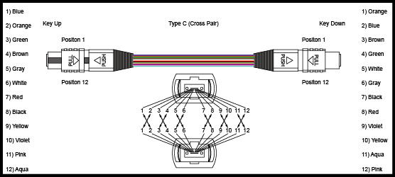
Method C uses Key Up to Key Down Adapters. This method uses straight patch cords and the same cassettes as in Method A. The difference is that the flip does not happen in the end patch cords but in the array cable itself. for example, Fiber 1 on one end is shifted to Fiber 2 at the other end of the cable. The Fiber 2 at one end is shifted to Fiber 1 at the opposite end etc. So it’s also complicated to properly manage the polarity of the links and to identify where the actual flipped array cord is placed in the link. Besides, it’s hard to extend the links. So this method is not suitable to be applied with emerging 40Gbps standards.

Conclusion
There are three methods to maintain MPO/MTP polarity. Network designers should evaluate each method before implementing to ensure the reliability, ease of installation, maintenance and reconfiguration as well as easy migration to higher data rates solutions like 40/100G Ethernet. It’s recommended that a method selected should better not be changed in an installation.
Originally published at www.fiber-optic-equipment.com
No comments:
Post a Comment