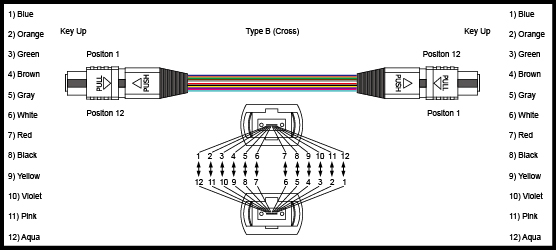
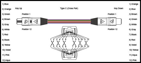
As the migration to 40G/100G Ethernet using parallel array transmission systems, the high-density MPO cables are widely used in the data center. In the connection, contamination even as small as 0.001 mm can cause the optical loss. Mating a contaminated connector to a clean connector will lead to poor performance and can damage the connection. So it’s important to test the link segments consisting of MPO array cabling and keep the cable clean. However, MPO cable testing and cleaning is full of challenges.
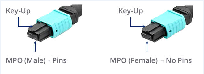
Why MPO cables testing and cleaning is not easy? First, MPO connectors are very sensitive to dirt and contamination. The ferrules are large and hard to clean and inspect. Most microscopes don’t have adapters for MPO connectors. Those microscopes with adapters for MPO connectors can only see a small section of the ferrule because they are adapted from single fiber microscopes. So you have to inspect the entire ferrule and every fiber. Second, cleaning is also a problem because of the designs of MPO connectors with pins and holes. Most dry cleaners can only clean the place between the pins. So dirt may increase around the pins or in the holes, which cause alignment problems. So remember often keep MPO connectors well covered and protected when not in use.
Calculate the Acceptable Attenuation
Calculate the acceptable total loss of the entire optical link so that you can find if the test result is good or bad. Do as the following steps with your link loss calculator:
- 1. Select the fiber type and test wavelength combination;
- 2. Select the unit of length in feet or meters;
- 3. Enter the total link length under test;
- 4. Enter the number of connections of each type (a pair of connectors counts as one connection);
- 5. Enter the number of splices (each connection counts as a connection plus a splice).
MPO Trunk Cable Testing Procedures
In this case, MPO connectors can be directly connect to the test equipment. That requires 12 output sources and either 12 input ports or an MPO port with a detector which can accept the light from 12 or 24 fibers. But at present this is not available. In the laboratory or factory settings, there are test equipment that can achieve this. Then, engineers use an MPO to LC fan-out cord to separate the trunk into single fiber channels for testing.
There are five basic steps for an MPO trunk cable testing (see figure 1):

Figure 1. set reference (three pictures above) and test MPO cable (two pictures below)
- 1. Find a test equipment where the input port can be changed to an LC or has an LC already.
- 2. Set a reference and there are three methods. Insert the known good cords into relative input ports and run an autotest (the above three pictures). If the loss is fewer than 0.1 dB (usually the maximum loss of LC connection is 0.2 dB), then the reference cords are good. This is critical to the test.
| Reference Method | Reference Cable | Connectors Included in Measurement | Estimated Reduction in Measured Loss | Estimated Increase in Errors |
| 1-Cable Method(test equipment compatible with connectors being tested) | 1, launch | 0 | 0 dB | 0 dB |
| 2-Cable Method(single fiber ferrule connectors, test equipment not compatible with connectors being tested) | 2, launch and receive | 1 | 0.2-1 dB | +/-0.2 dB |
| 3-Cable Method(male/female or plug and jack connectors, test equipment compatible with connectors being tested) | 3, launch, receive and “golden cable” | 2 | 0.3-1.5 dB | +/-0.25 dB |
- 3. After setting the reference, remove the middle test reference cords and connect fan-out cables with an MPO trunk cable.
- 4. Measure and record the loss every pair of LC connectors at the left side.
- 5. Measure and record the loss every pair of LC connectors at the right side.
Summary
Compare the test result with calculated acceptable attenuation, If the test result is not ideal,that may be caused by the contamination, defects in the cable plant, or improper test equipment usage. Then you should better check connector end-faces for dirt and defects, and check link segment for broken fiber, poor splices and tight bends. MPO connectors are very likely to be contaminated because of fibers, number of connections and tight loss budgets. To keep MPO cabling system perform well, frequent cleaning and inspection with one-click cleaner are required.
Originally published at www.fiber-optic-equipment.com
