Showing posts with label multimode. Show all posts

Tuesday, February 7, 2017

Does Multimode SFP Work Over Single-mode Fiber Cable?

When you prepare to connect some SFPs with fiber patch cords, you may find SFPs are multimode modules while your fiber cables are single-mode. Try to connect those optics to fiber cable, but no green light and the link fails. So multimode SFPs can’t work over single-mode fiber cables. To avoid the wasting of time and money, you should better know well about single-mode and multimode SFPs and fiber patch cords.
Single-mode and Multimode SFP
SFP, small form factor pluggable transceiver, can support the data rate up to 1Gbps. SFPs can be divided into single-mode and multimode modules.
For single-mode SFPs, there are “LX” for 1310 nm and “EX” “EZX” for 1550 nm. Single-mode SFPs are designed to transmit signals over long distances. For example, Cisco GLC-LH-SM-15 compatible 1000BASE-LX/LH SFP 1310nm 15km DOM transceiver, main product information is shown as follows:
  • Wavelength: 1310 nm
  • Interface: LC duplex
  • Max Cable Distance: 15 km
  • Max Data Rate: 1000Mbps
  • Cable Type: SMF
Comparatively, multimode SFPs are identified with “SX”. This kind of optics is specially for short distance data transmission. For instance, Cisco GLC-SX-MM compatible 1000BASE-SX SFP 850nm 550m transceiver, this is a typical multimode SFP.
  • Wavelength: 850 nm
  • Interface: LC duplex
  • Max Cable Distance: 550m over OM2 MMF
  • Max Data Rate: 1000Mbps
  • Cable Type: MMF

Single-mode Fiber Cable and Multimode Fiber Cable
Fiber patch cables are used to connect transceivers on your switch/device. You have to buy the right fiber cable type for your optics. Fiber cable has two different categories: single-mode and multimode.
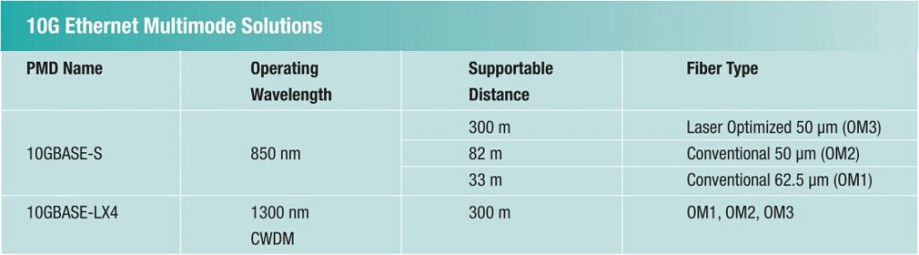
Generally, single-mode fiber cable can support further distance because of lower attenuation, but the price is higher. While multimode fiber cable has a larger core, usually multimode fiber cable is constructed in 50/125 and 62.5/125. It allows multiple modes of light to propagate. When the light passes through the core, the light reflections increases and more data can be transmitted at given time. As the high dispersion during signal transmission, the link distance gets reduced. So multimode fiber cable is for short distance application. Multimode fiber cable is a little more complex than single-mode fiber cable since it includes four different types of OM1, OM2, OM3, OM4. OM1 and OM2 fiber patch cable can support the data rate up to 10Gbps. OM3 and OM4 are laser optimized so that they can be used in high density data center to support the data rate of 40Gbps and 100Gbps. The following table shows how long each kind of fiber cable can reach running at different data rate.

Note: “SR” implies multimode 10Gpbs SFP+.
For more information about single-mode and multimode fiber cable, you can refer to my previous articles:
What Is Single Mode Fiber?
What Are OM1, OM2, OM3 and OM4?

Solutions for Multimode SFP

If you have Cisco Catalyst 3650 WS-C3650-48PS switches with 4x1G uplink ports, to build a 300m-network link, you are gonna purchase fiber patch cable and SFP modules. What kind of optical equipment should you choose?
As to the SFP module, you need Cisco GLC-SX-MM 1000BASE-SX SFP. Or you can spend less money on third-party SFPs with 100% compatibility. Next step, you need to find suitable fiber patch cable to match this type of SFP. Since 1000BASE-SX SFP is multimode, of course you need multimode fiber cable. Considering the distance of 300 meters, OM1 can only reach 275 meters. So OM2 is the best choice for it’s the cheapest and can reach 550 meters.

Conclusion
It’s obvious that multimode SFPs can’t work over single-mode fiber cables. When buying SFPs, watch the standards on the label carefully and find if it’s “SX” or “LX”, “EX”. If it shows “SX”, then find multimode fiber patch cable. It’s not very difficult to choose right cable for your SFP modules.
Originally published at www.fiber-optic-equipment.com

Thursday, February 2, 2017

What Can We Get From Fiber Cable Jacket?

Fiber optic cable is applied as the most advanced communication medium by more and more users. Compared with copper cable, it can support more and better optical signal transmission of voice, data, video, etc. and offer many other advantages. When purchasing fiber optic cables, you must see the cable jacket at first. So what information does the outside jacket tell? What type of cable jacket should you select? Come with me to find the secrets of fiber cable jacket.
Fiber Cable Jacket Introduction
Fiber optic cable is constructed very complicated from the inside core, cladding, coating, strengthen fibers to the outside cable jacket. The core made of plastic or glass is the physical medium for optical signal transmission. As bare fiber can be easily broken, cable outer jacket is needed for fiber protection. The cable jacket is the first line of moisture, mechanical, flame and chemical defense for a cable. Without the jacket, fiber optic cables are very likely to be damaged during and after installation.

Fiber Cable Jacket Characteristics
In most situations, robust cable jacket is better because the environment above or underground may be harsh. For better applications, you’d better take cable jacket seriously. Cable jacket is not as easy as you think. There are many characteristics you need to consider. Except the flexibility, it should withstand very low and high temperature. Whether the cable jacket has the good features of chemical and flame resistance. All these characteristics depend on cable jacket materials.
Fiber Cable Jacket Materials
Cable jacket is made of various types of materials. As mentioned above, the cable jacket should stand the test of different environmental conditions, including the harsh temperature, the sun & the rain, chemicals, abrasion, and so on. The following shows several common cable jacket materials for your reference.
PE (Polyethylene)—PE is the standard jacket material for outdoor fiber optic cables. It has excellent properties of moisture and weather resistance. It also has the good electrical properties over a wide temperature range. Besides, it’s abrasion resistant.
PVC (Polyvinyl Chloride )—PVC is flexible and fire-retardant. It can be used as the jacket materials for both indoor and outdoor cables. PVC is more expensive than PE.
LSZH (Low Smoke Zero Halogen)—LSZH jacket is free of halogenated materials which can be transformed into toxic and corrosive matte during combustion. LSZH materials are used to make a special cable called LSZH cable. LSZH cables produce little smoke and no toxic halogen compounds when these cables catch fire. Based on the benefits, LSZH cable is a good choice for inner installations.
Fiber Cable Jacket Color
Fiber cable jacket color depends on the fiber cable type. Fiber cable includes single-mode and multimode types. For single-mode fiber cable (Blog about single-mode fiber cable please read my blog What Are OM1, OM2, OM3 and OM4?), the jacket color is typically yellow. While for multimode cable ( more details on multimode fiber cable ), the jacket color can be orange (OM1&OM2 cable), aqua (OM3 cable) and purple (OM4 cable). For outside plant cables, the jacket color is black.
How to Choose Fiber Cables?
To choose a fiber optic cable depends on your own applications. I’ll talk about this from two sides of jacket color and jacket material. The cable jacket color is not just for good looking. Different color means different fiber mode. Which one suits you the most, the yellow or orange fiber cable? You should know well about the color codes before buying your fiber cables. What’s more, you should also consider the installation requirements and environmental or long-term requirements. Where will be your fiber cables installed, inside or outside the building? Will your cables be exposed to hash environment very long? This can help you decide which jacket material is the best.
Summary
As a popular data transmission medium, fiber cable plays an important role in communication field. To some degree, the success of fiber connectivity lies in a right fiber cable. How to buy suitable fiber optic cables? This article describes the method from cable jacket. When selecting fiber cable, many other factors still need to be considered. Hope you can get your own fiber cable.
Originally published at www.fiber-optic-equipment.com

Wednesday, June 29, 2016

The New 10G Multimode Optical Solution – 10GBASE-LRM

10 Gigabit Ethernet has been applied for a long time in data centers and enterprise LANs. For 10G Ethernet connection, there are both single-mode and multimode solutions. First let’s see the original multimode solutions and supportable distances for 10G Ethernet.
10G-multimode solution-supportable-distance
10GBASE-S operates at 850nm wavelength. It can support up to 300m distance over laser-optimized OM3. This makes it a popular standard for data centers and cooperate backbones. For the conventional OM1 and OM2 which are not optimized for laser transmission, the furthest supportable distance is 33 m and 82 m. So these two solutions are only used in equipment rooms or small data centers.
10GBASE-LX4 was specified to support 300 m over three cable types. So it relies on coarse wavelength division multiplexing (CWDM) which is more complex and expensive technology. 10GBASE-LX4 operates at 1300nm wavelength and that requires additional cost on mode-conditioning patch cords (MCPCs).
The high cost and relatively slow adoption of 10GBASE-LX4 drive the development of a new standard—10GBASE-LRM. 10GBASE-LRM is developed to offer a longer reach for conventional fiber cables at a lower cost and smaller size than 10GBASE-LX4. The following will talk about 10GBASE-LRM from three sides.
Transmission Distance
On condition the supporting distance, 10GBASE-LRM can only support 220 m. It’s suitable for LAN networks within buildings. But a cabling survey provides that for 10G network, the distance is not able to address 30% of in-building channels.
Electronic Dispersion Compensation
The key to the long reach of 10GBASE-LRM on conventional multimode fiber is electronic dispersion compensation (EDC). EDC is deployed as an integrated circuit that acts like a complex filter on the received signal from the optical fiber. The purpose is to extend the maximum supportable distance. 10GBASE-LRM applies EDC technology and is therefore independent of the optical wavelength. 10GBASE-LRM operates at 1300 nm.
EDC chips is added to a linear detector in the receiver. As an additional component, it increases cost, consumes power and wastes heat. It can only work as intended in conjunction with a linear detector and amplifier. Because the EDC device must operate on a faithful analog rendition of the optical waveform in the fiber. For 10GBASE-LRM, to reproduce the optical waveform with precision, extra requirements and cost on the receiver design are needed.
Multiple Transmit Launch Conditions
In order to improve the chances of operating at a higher bandwidth, 10GBASE-LRM relies on multiple transmit launch conditions.
One launch is achieved by using mode-conditioning patch cord. The other launch is produced using a regular multimode patch cord. Through the two launches, different modes can be achieved and a favorable operating condition can be easily found.
There are four possible patch cord combinations at both ends of the channel. The preferred launch uses MCPCs on both ends. This process requires a test for link stability for each configuration. The user should shake and bend the patch cord at the transmit end while observing channel health indicators at the receive end. The shaking and bending of the cords causes changes to the received waveform which the receiver must tolerate in normal operation. If there were transmission errors, then users should change another launch. The errors indicate that the channel is operating near or beyond the limit of the receiver’s capability and the link may fail in operation.
launch-conditions-for-10gbase-lrm
However, the 10GBASE-LRM standard’s committee refuse to implement this channel test. So the burden of the shaking and bending lies on the users. It’s not good for the popularity of 10GBASE-LRM.
Comparison of Several 10G Transceivers Cost
The following will compare the cost of 10G transceivers from several sides, including laser, receiver, package and cords.
Laser: 10GBASE-LRM uses 1310nm fabry perot lasers, which cost fewer than 10GBASE-L’s and 10GBASE-LX4 DFB lasers, but more than 10GBASE-S’s 850nm VCSELs. 10GBASE-LRM requires tighter transmitter waveform control to limit the transmit waveform dispersion penalty that EDC can’t compensate. Thus, it reduces transmitter yields and increases cost.
Receiver: 10GBASE-LRM adds EDC chip cost to receiver and needs a linear detector and amplifier instead of other cheap digital equipment.
Package: 10GBASE-LRM requires a smaller package than 10GBASE-LX4. However, not like 10GBASE-S, 10GBASE-LRM requires higher-cost single-mode transmitter alignment for compatibility with mode conditioning patch cords.
Cords: 10GBASE-LRM needs mode conditioning patch cords for reliable link operation. And the cost is much higher than regular SMF or MMF fiber optic patch cords.
Through the comparison among these 10G optical transceivers, you may find which one costs fewer. 10GBASE-LRM transceiver is cheaper than 10GBASE-LX4, more expensive than 10GBASE-L and 10GBASE-S transceivers.
Conclusion
10GBASE-LRM is a multimode solution for 10 Gigabit Ethernet. Based on the above content, 10GBASE-LRM has some advantages over 10GBASE-LX4. It offers lower cost and smaller package. But the distance and reliability are not very ideal. Compared with 10GBASE-S, 10GBASE-LRM is not so good as to the cost, simplicity, reliability and distance capability. FS.COM provides various types of cost-effective 10GBASE transceivers, such as 10GBASE-LR, 10GBASE-SR, 10GBASE-ER, etc. Other compatible brands like Cisco, Juniper, Arista, Brocade are also available. Among so many choices, you must choose the most suitable solution for your network connection.
Originally published at www.fiber-optic-equipment.com

Saturday, January 16, 2016

What Should You Know Before Using an OTDR?

OTDR, the optical time domain reflectometer, is the most important investigation tool for optical fibers. It’s applied in the measurement of fiber loss, connector loss and for the determination of the exact place and the value of cable discontinuities. It’s the only device which can verify inline splices on concatenated fiber optic cables and locating faults.
To know how to use OTDR for the fiber investigations, first you should know the structure and working principle of OTDR equipment. When a short light pulse transmits into the fiber under test, the time of the incidence and the amplitude of the reflected pulses are measured. The commonly used pulse width ranges from nanosecs to microsecs, the power of the pulse can exceed 10 mW. The repetition frequency depends on the fiber length, typically is between 1 and 20 kHz, naturally it is smaller for longer fibers. The division by 2 at the inputs of oscilloscope is needed since both the vertical (loss) and the horizontal (length) scales correspond to the one-way length.
jdsu-mts-4000-otdr
Besides, to use an OTDR successfully, you should also know how to operate the instrument. The following is about the experiences collected from some experienced people who use OTDRs during installation and for maintaining telecommunication networks.
Keep Connectors Clean
Before use OTDR, first, you should watch out if the connectors are clean. If it’s dirty, then clean it. Otherwise, it will make measurements unreliable, noisy or even impossible. What’s worse, it may damage the OTDR.
Check the Connector or the Patch Cord
Check whether the patch cord, the module, and the fiber under test are single-mode or multimode. To test the patch cord, activate the laser in the CW (Coarse Wavelength) mode and measure the power at the end of the patch cord with a power meter. This should be between 0 and - 4 dBm for most single-mode modules and wavelengths.
Set the Range
The range is the distance over the cable which the OTDR will measure. The range should be longer than the cable you are testing. For example, if your link is 56.3 km long, choose 60 km. For distances greater than approximately 15 km, make your first measurement in longhaul mode, otherwise use shorthaul.
Determine the Wavelength
Usually single-mode is set for 1310 nm or 1550 nm, and multimode is set for 850 nm or 1300 nm.
Averages of Noisy Traces
If the trace is very noisy, increase the number of averages. Usually 16-64 averages are adequate. To improve the signal to noise ration of the trace, the OTDR can average multiple measurements, but averaging takes time. So try to average over a longer time.
Realtime Mode
In this mode, you can modify parameters only if you stop a measurement explicitly. So it avoids you to erase a trace averaged over a long time by accident. You use realtime mode to check your connection, the quality of splices, and whether a fiber is connected. Start in automatic mode, then switch to realtime mode and select the most suitable parameters.
Adjust the Refractive Index
If you know the exact physical length of the fiber under test, you can measure the refractive index. Start with the refractive index 1.5000. Place a marker at the end of the fiber. Then select the refractive index function and adjust it until the displayed marker position is equal to the known fiber length. Then, the effective refractive index will be displayed.
Macrobending Loss
Single-mode fibers (1550 nm) are very sensitive to macrobending such as a tight bend or local pressure on the cable. It doesn’t always happen at this wavelength of 1310 nm. So characterize your link at both wavelengths.
OTDRs are invaluable test instruments. Maybe a small mistake will cause serious damage to this equipment. So before use it, you should better know it as detailed as possible to avoid any loss because of innocence and make full use of it in optical fiber events.
Originally published at http://www.articlesxpert.com/article/1182251/what-should-you-know-before-using-an-otdr/