10 Gigabit Ethernet has been applied for a long time in data centers and enterprise LANs. For 10G Ethernet connection, there are both single-mode and multimode solutions. First let’s see the original multimode solutions and supportable distances for 10G Ethernet.

10GBASE-S operates at 850nm wavelength. It can support up to 300m distance over laser-optimized OM3. This makes it a popular standard for data centers and cooperate backbones. For the conventional OM1 and OM2 which are not optimized for laser transmission, the furthest supportable distance is 33 m and 82 m. So these two solutions are only used in equipment rooms or small data centers.
10GBASE-LX4 was specified to support 300 m over three cable types. So it relies on coarse wavelength division multiplexing (CWDM) which is more complex and expensive technology. 10GBASE-LX4 operates at 1300nm wavelength and that requires additional cost on mode-conditioning patch cords (MCPCs).
The high cost and relatively slow adoption of 10GBASE-LX4 drive the development of a new standard—10GBASE-LRM. 10GBASE-LRM is developed to offer a longer reach for conventional fiber cables at a lower cost and smaller size than 10GBASE-LX4. The following will talk about 10GBASE-LRM from three sides.
Transmission Distance
On condition the supporting distance, 10GBASE-LRM can only support 220 m. It’s suitable for LAN networks within buildings. But a cabling survey provides that for 10G network, the distance is not able to address 30% of in-building channels.
Electronic Dispersion Compensation
The key to the long reach of 10GBASE-LRM on conventional multimode fiber is electronic dispersion compensation (EDC). EDC is deployed as an integrated circuit that acts like a complex filter on the received signal from the optical fiber. The purpose is to extend the maximum supportable distance. 10GBASE-LRM applies EDC technology and is therefore independent of the optical wavelength. 10GBASE-LRM operates at 1300 nm.
EDC chips is added to a linear detector in the receiver. As an additional component, it increases cost, consumes power and wastes heat. It can only work as intended in conjunction with a linear detector and amplifier. Because the EDC device must operate on a faithful analog rendition of the optical waveform in the fiber. For 10GBASE-LRM, to reproduce the optical waveform with precision, extra requirements and cost on the receiver design are needed.
Multiple Transmit Launch Conditions
In order to improve the chances of operating at a higher bandwidth, 10GBASE-LRM relies on multiple transmit launch conditions.
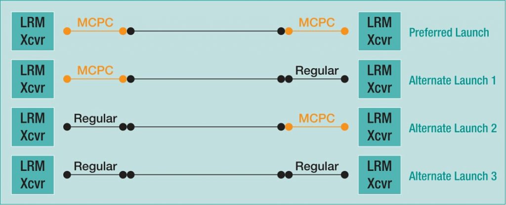
One launch is achieved by using mode-conditioning patch cord. The other launch is produced using a regular multimode patch cord. Through the two launches, different modes can be achieved and a favorable operating condition can be easily found.
There are four possible patch cord combinations at both ends of the channel. The preferred launch uses MCPCs on both ends. This process requires a test for link stability for each configuration. The user should shake and bend the patch cord at the transmit end while observing channel health indicators at the receive end. The shaking and bending of the cords causes changes to the received waveform which the receiver must tolerate in normal operation. If there were transmission errors, then users should change another launch. The errors indicate that the channel is operating near or beyond the limit of the receiver’s capability and the link may fail in operation.

However, the 10GBASE-LRM standard’s committee refuse to implement this channel test. So the burden of the shaking and bending lies on the users. It’s not good for the popularity of 10GBASE-LRM.
Comparison of Several 10G Transceivers Cost
The following will compare the cost of 10G transceivers from several sides, including laser, receiver, package and cords.
Laser: 10GBASE-LRM uses 1310nm fabry perot lasers, which cost fewer than 10GBASE-L’s and 10GBASE-LX4 DFB lasers, but more than 10GBASE-S’s 850nm VCSELs. 10GBASE-LRM requires tighter transmitter waveform control to limit the transmit waveform dispersion penalty that EDC can’t compensate. Thus, it reduces transmitter yields and increases cost.
Receiver: 10GBASE-LRM adds EDC chip cost to receiver and needs a linear detector and amplifier instead of other cheap digital equipment.
Package: 10GBASE-LRM requires a smaller package than 10GBASE-LX4. However, not like 10GBASE-S, 10GBASE-LRM requires higher-cost single-mode transmitter alignment for compatibility with mode conditioning patch cords.
Cords: 10GBASE-LRM needs mode conditioning patch cords for reliable link operation. And the cost is much higher than regular SMF or MMF fiber optic patch cords.
Through the comparison among these 10G optical transceivers, you may find which one costs fewer. 10GBASE-LRM transceiver is cheaper than 10GBASE-LX4, more expensive than 10GBASE-L and 10GBASE-S transceivers.
Conclusion
10GBASE-LRM is a multimode solution for 10 Gigabit Ethernet. Based on the above content, 10GBASE-LRM has some advantages over 10GBASE-LX4. It offers lower cost and smaller package. But the distance and reliability are not very ideal. Compared with 10GBASE-S, 10GBASE-LRM is not so good as to the cost, simplicity, reliability and distance capability. FS.COM provides various types of cost-effective 10GBASE transceivers, such as 10GBASE-LR, 10GBASE-SR, 10GBASE-ER, etc. Other compatible brands like Cisco, Juniper, Arista, Brocade are also available. Among so many choices, you must choose the most suitable solution for your network connection.
Originally published at www.fiber-optic-equipment.com


