Friday, May 27, 2016

ABCs of Optical Switch

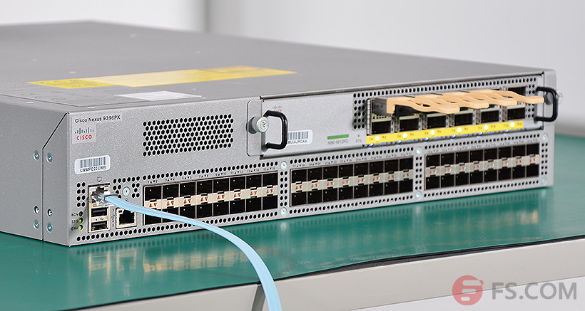
Optical networking technology has solved the problem of increasing demand for higher transfer data rates and larger bandwidths. In optical network, optical fiber is the fundamental medium of transmission. However, switching, signaling and processing functions are accomplished electronically. So optical switches are naturally developed. Optical switches are widely used for optical protection, test systems (as shown in the following figure), and remotely reconfigurable add-drop multiplexers, etc.
fs.com-switch
Figure 1. Switch for FS.COM transceiver compatibility test
Two Types of Optical Switches
An optical switch is simply a switch which accepts a photonic signal at one of its ports and send it out through another port based on the routing decision made. There are two kinds of optical switches, including O-E-O (optical–electrical–optical) and the O-O-O (optical–optical–optical) also called all optical switch. OEO switch requires the analogue light signal first converted to a digital form to be processed and routed before being converted back to an analogue light signal. While OOO switching is done purely through photonic means.
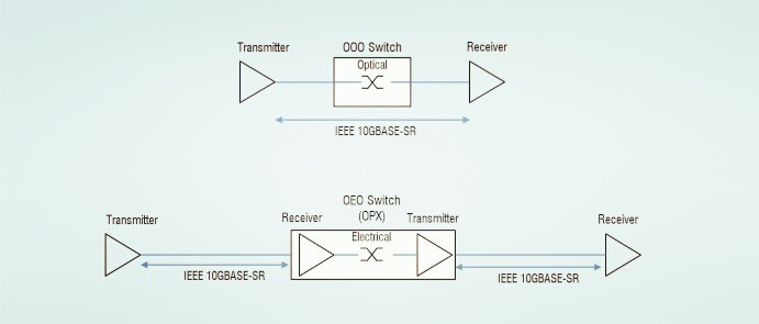
oeo and ooo
Advantages of Optical Switches
Compared with electrical switches, optical switches have many advantages.
On one hand, optical switches can save floor space and power consumption significantly. They can save up to 92 percent space and 96 percent power. If translating power savings into cost, it means 3 kw can be reduced for each rack. This can save the carrier from expensive diesel power generators, rectifiers and batteries, the monthly maintenance costs for these devices and the purchasing and maintenance of cooling equipment for these devices.
On the other hand, optical switches are a lot more scalable and faster than electric switches, as all-optical switches are protocol and bit rate independent. Because of the scalability and flexibility all-optical switches have, so transfer rates will not be affected bit rate limitations of switching equipment.
Problems of Optical Switches
Despite those advantages, optical switches still have some problems.
Current optical switching technology can’t realize the technology that photonic signals can be as stored as easily as electrical signals. It is possible to store them using fiber delay lines, as light take a certain time to travel through lengths fiber (200,000 km per second in silica). That means a 10000 bit frame traveling at 10G b/s requires 200m of fiber. This is both expensive and impractical. And once a signal is put through a delay line, it cannot be processed until it comes back out. A solution to this is through adding switches within the lines, but that needs more costs.
The other problem with all – optical switching is that it cannot process header information of packets, especially at such high speed which the signals travel at. The maximum speed electronic routers currently can operate is at 10 Gb/s while optical signals can travel up to 40/100G or even higher. Thus, the routers will not be able to process the signals as fast as the transmission.
Applications of Optical Switches
Optical switches are widely applied in the network.
First, optical switches are used in high speed network which requires very high switching speeds and also requires very large switches to handle the amount of traffic. So switches are likely used within optical cross-connects (OXC). OXC are similar to electronic routers which forward data using switches. An OXC may contain a whole series of optical switches.
Second, optical switches are used for switching protection. If a fiber fails, the switch allows the signal to be rerouted to another fiber before the problem occurs. But this will take milliseconds including detecting the failure, informing the network and switching. Normally this operation requires a 1x2 switch but with complicated cross-connects hundreds may be required.
Third, optical switches can be also used for external modulators, OADM (optical add-drop multiplexers), network monitors and fiber optic component testing.
Conclusion
As the demand for video and audio increasing the challenge of data capabilities and high bandwidth of networks, optical network is absolutely the most cost-effective solution. Optical switches can provide the customers with significant power, space and cost savings. Today, the optical switch market is dominated by several companies, such as Cisco, HP, Arista, Juniper. In early days, original optical transceivers were required to be plugged into these switches. Later, to save the cost, third-party optical transceivers were produced. If you need optical transceivers compliant with these switches, please visit FS.COM.
Originally published at www.fiber-optic-equipment.com
Friday, May 20, 2016

How to Ensure a High Quality PLC Splitter?

PLC (Planar Lightwave Circuit) splitter is an important component in PON (passive optical network) where a single optical input is split into multiple outputs. This makes it possible to deploy a Point to Multi Point physical fiber network with a single OLT (optical line terminal) port serving multiple ONTs (optical network terminal). The most common split ratios are 1:N or 2:N. N represents the output ports, usually as 2, 4, 8, 16, etc. The optical input power is distributed uniformly across all output ports. The PLC splitter shares the cost and bandwidth of the OLT and reduces fiber lines. This article will tell about how to keep a high quality PLC splitter from manufacturing to testing sides.
plc-assured-program
Key Manufacturing Steps of PLC Splitter
PLC splitter is composed by many miniature parts. Among them, there are three main components: fiber array for the input and output, and the chip. These three main components decide whether the PLC splitter is of good quality or not. Let’s see the key manufacturing steps of a PLC splitter.
Step1. Components Preparation
The PLC circuit chip is designed and embedded on a piece of glass wafer. Each end of the glass wafer is polished to ensure high precision flat surface and high purity. The V-grooves are grinded into a glass substrate. A single fiber or multiple ribbon fiber is assembled onto the glass substrate. This assembly is polished.
Step2. Alignment
After preparing the three components, it’s time for alignment. The input and output fiber array is set on a goniometer stage to align with the chip. Physical alignment between the fiber arrays and the chip is monitored through the power level output from the fiber array. Epoxy is then applied to the fiber array and the chip to affix their positions.
Step3. Cure
The assembly will be placed in a UV chamber to be fully cured at a controlled temperature.
Step4. Packaging
The bare aligned splitter is assembled into a metal housing where fiber boots are set on both ends of the assembly. A temperature cycling test will be done for a final screening to ensure the final product condition.
Step5. Testing
Optical testing items include insertion loss, uniformity and polarization dependent loss. This testing is to ensure the splitter compliant to the optical parameters in GR-1209 CORE specification.
Testing Standards of PLC Splitter
Then how to determine the quality of a PLC splitter? The GR-1209 standards provides comprehensive optical performance criteria. The following will introduce these specifications such as optical bandpass, insertion loss, return loss, uniformity and directivity.
Optical Bandpass
In a PON system, the downstream transmission uses 1490nm wavelength and 1310nm wavelength for the upstream transmission. Besides, the requirement for RF video overlay and network testing/maintenance should also be considered. The transmission wavelength for RF video is 1550 nm. And the wavelengths for networking testing and maintenance are 1550 nm and 1625 nm. So the standard opterating wavelength for a PON splitter is determined as 1260~1650 nm which covers most of the optical bands.
Insertion Loss
The optical splitter has the largest attenuation in a PON system. The insertion loss transfers from the input port to the output port. In order to conserve the power of a PON system, the insertion loss should be reduced to the least. There are formulas to calculate the maximum insertion loss of an optical splitter in a PON system according to the GR-1209 standard: 0.8 + 3.4 log2N (for 1xN optical splitter) and 1.0 + 3.4 log2N. To decide if the insertion loss is in the qualified range, you need to choose one formula to calculate.
Return Loss
Optical return loss is part of the power transferred from one input port back to the same input port or from an output port back to the same output port. A high return loss will influence the data transmission quality. So it’s important to minimize the noise to keep the PON system power for a better transmission.
Uniformity
Uniformity means the maximum insertion loss value between one input port and any two output ports or between two input ports and one output port. This can ensure that the transmission power at each splitter output port is the same in a PON system to simplify the network design.
Directivity
Directivity is the part of power transferred from one input port to another input port or from an output port to another output port. For a 2xN optical splitter, when light injects into one of the input ports, light doesn’t only propagate out of the output ports. Some of the light propagates back through the second input port. And when the light injects into one of the output ports, light propagates back through the other output ports. In a bidirectional transmission system such as a PON, directivity is useful to reduce signal crosstalk. A high directivity value will increase the insertion loss due to the optical power loss.
Conclusion
FS.COM provides a variety of PLC splitters including 1×2, 1×4, 1×8, 1×16, 1×32, 1×64; 2×2, 2×4, 2×8, 2×16, 2×32, 2×64 in various package options, which offer cost-effective solutions for your applications. To ensure high performance, we have set a quality assurance program for PLC splitter. We always care every detail both in manufacture and testing. For detailed information, please contact us via sales@fs.com.

Originally published at www.fiber-optic-equipment.com
Friday, May 13, 2016

Brief Introduction of Fiber Optical Splitters

Fiber optic splitters are quite important in today’s optical network. Splitters can help users maximize the functionality of optical network circuits. A fiber optical splitter is a passive optical device that can split, or separate, an incident light beam into two or more light beams. These beams may or may not have the same optical power as the original beam. The outputs of a splitter can have various degrees of throughput. And that is very useful to decide whether the splitter is used for network monitoring or for a loss budget in a passive optical network (PON) architecture when designing optical networks. This article will give brief introduction of fiber optical splitter.
Two Types of Fiber Optical Splitters
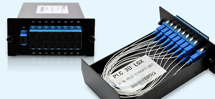
There are two kinds of the most commonly used fiber optical splitters. And they are planar lightwave circuit (PLC) and fused biconical taper (FBT). PLC splitters (as shown in the following picture), from the name, it’s easy to find out that PLC splitters are based on planar lightwave circuit technology. It uses an optical splitter chip to divide the incoming signal into multiple outputs. It consists of three layers including a substrate, the waveguide, and the lid. The waveguide layer accepts the incoming optical signal and passes it to the outputs. FBT splitters are fused with a heat source similar to a fusion splice. Fibers are aligned in a group to create a specific location and length and will be fused with heat to meet the desired parameters such as insertion loss. Fused fibers are put in a V-shaped groove and fixed in a silica tube with a mix of epoxy and silica powder to get the proper heat.
1x16-Fiber-PLC-Splitter
Fiber Optical Split Ratios
Fiber optical splitters vary in numbers of inputs and outputs. The split ratios are based on the network use of fiber optical splitters. In a PON architecture, it uses splitters to split a single fiber into multiple fibers to feed as many as 64 end users. A typical split ratio in PON application is 1:32, or one in coming fiber split into 32 outputs.
Large split ratios like 1:32 or 1:64 are often found in some kind of housing. That’s because with so many fibers related to these splitters, a platform should be used to manage the splitter modules, patch modules, patch cables, etc. Most often a high-density fiber bay is required so that the splitters can be all placed in a distribution site or a PON enclosure. The PON cabinet plays a significant role in today’s applications since the space is so limited. When it comes to a high-density frame with varying split ratios and large number of patch cords, the distribution frame is critical for a good cable management.
Cost Saving in FTTx/PON Applications
As the city grows and subscribers increase, the network architect must deal with multiple distribution points and backhaul. To meet so many subscribers’ requirements, the flexibility in head-end locations, distribution points and split ratios becomes more significant. To network service provider, saving capital and operational costs is important.
On one side, fiber optical splitters can save fiber cost by reducing the fiber usage and that’s why they are so important in FTTx/PON networks. Using a single fiber to feed as many as 64 end users significantly reduces the fiber quantity. On the other side, the long-term operation costs can’t be ignored either in optical network splitter applications. That’s one of PON’s advantages. For example, it can decrease the power consumption.
Another way to save cost is to ease maintenance and increase the flexibility for smaller split ratios, which lead to more bandwidth per subscriber. For example, a service provider would likely need to split the optical terminal line (OLT) with a 1:2 splitter, and adjust the split ratios from there based on delivery to residential (1:32). These multiple split ratios can create flexibility in the network as long as the utilization of transport electronics such as OLT is concerned. Loss budget can be greatly influenced by the use of multiple splitters.
Conclusion
From the above content, to run a network architecture, the network success and cost should be paid attention. And fiber optical splitter is such a good device to increase the efficiency of optical infrastructure and save the capital and future operational cost.
Originally published at www.fiber-optic-equipment.com
Friday, May 6, 2016

The Newly Released 25GbE Ethernet Standard

As the increasing bandwidth requirements of private and public cloud data centers and communication service providers, 25Gbps Ethernet over a single lane will have a significant impact on server interconnect interfaces. It may become the new upgrade path to 100G (10G-25G-100G instead of 10G-40G-100G). This article will give brief introduction about 25GbE Ethernet.
What’s 25GbE Ethernet
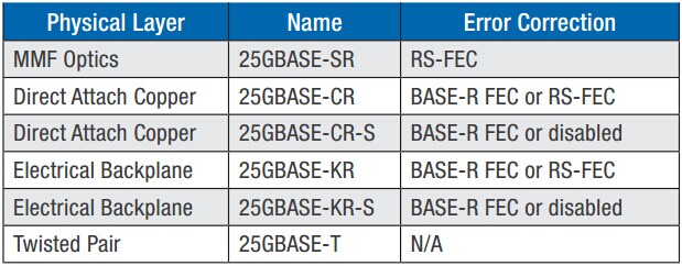
25GbE Ethernet standard is proposed for connectivity in the data centers. Because of the increasing demand for higher speed network performance and maintaining Ethernet economics, IEEE agreed to support the development of 25GbE standard in June 2014. 25G Ethernet is defined for 100GbE implemented as four 25Gbps lanes running on four fiber or copper pairs. 100G Quad small for-factor pluggable transceiver (QSFP28) have four lasers, each transmitting 25Gbps. The twisted pair pair standard was derived from 40GbE standards development. The following table shows the main upcoming interfaces for 25Gbps.
25G-strandard-interface
Number of Lanes 40G QSFP+ interface is constructed from four parallel links. Extending QSFP+ onto fiber requires four parallel 10Gb streams to transport this to the receiving QSFP+ parallel optics. The data transmission is achieved by four lanes which significantly reduce switch port density per switching chip and increases the cost of cabling and optics. While the 25GbE standard requires only a single lane, while delivering 2.5 times more throughput compared to current 10GbE solutions and significantly saving the cost compared to 40GbE solutions.
Form Factors The 25GbE physical interface specifications support the form factors including QSFP28 and SFP28. QSFP28 has four lanes and each lanes supports 25 Gbps speed. SFP28 has only one lane and it also supports 25 Gbps speed. Current switch doesn’t support 25G SFP28 port. So the solution for 25G is to use a breakout cable that allows four 25GbE ports to connect to a 100GbE QFSFP28 switch port.
Benefits of 25GbE Ethernet
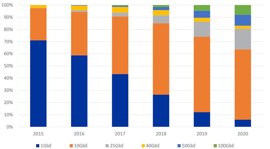
First, more data and switch port density. Compared with 10G solution, 25GbE standard can provide 2.5 times more data. And it can also offer 4 times switch port density compared to 40G solution. Second, save the cost. Since it can provide greater port density, fewer ToR switches and cables are needed. In that way, it reduces the construction cost compared with 40GbE. Third, it features lower power and smaller footprint requirements. Due to these special benefits, 25GbE is believed to be popular in no time. According to a recent five-year forecast, it’s said that annual shipments of 25GbE ports will be 2.5 times greater than 40GbE ports by 2018.
25G-forecast
25G Solutions
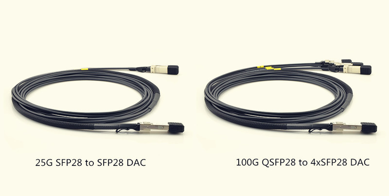
Fiberstore (FS.COM) has released 25G DAC (direct attach copper) cables which include 100G QSFP28 to 4xSFP28 and 25G SFP28 to SFP28 with the length from 1 m to 5 m. QSFP28 refers to the 100G DAC cable using the QSFP+ form factor, and SFP28 refers to the 25G DAC cable using the SFP+ form factor. The form factor remains the same but the new standard will require improved cables and connectors capable of handling additional bandwidth. Existing QSFP+ and SFP+ cable assemblies are not compatible with QSFP28 and SFP28 ports. 25G DAC is designed as the low-cost copper connection for ToR switches.
25G-dac cable
It’s certain that Fiberstore will soon release 25GBASE-T interface equipment. 25GBASE-T can support 30 meters long reach with low cost. It’s a cost-effective solution for ToR server connections using point-to-point patch cords, and enable End of Row (EoR) or Middle of Row (MoR) by using the 30 meter structured cabling. The connection can be achieved with the common use of RJ45 plug and connector. Compared with 25G DAC, it seems to be a more suitable way.
Conclusion
25GbE can provide up to 2.5 times faster performance than existing 10GbE connections while maximizing the Ethernet controller bandwidth/ pin and switch fabric capability. It can also provide greater port density with lower cost compared to 40GbE solutions. It’s analyzed that 25G will limit the deployment of 40G QSFP+ ports. By now, FS.COM has released 100G QSFP28 to 4xSFP28 and 25G SFP28 to 25G SFP28 DAC cables for 25G network. In the near future, there will more equipment for 25G including 25GBASE-T transceiver. Let’s look forward to it.
Originally published at www.fiber-optic-equipment.com