Today, data centers are being built to support 40G/100G transmissions. MPO/MTP interface patch cables are created to support 40G/100G data rates. Different from traditional 2–fiber configurations, with one send and one receive, 40G & 100G Ethernet implementations over MPO/MTP fibers use multiple parallel 10G connections that are aggregated. 40G uses four 10G fibers to send and four 10G fibers to receive, while 100G uses ten 10G fibers in each direction. To ensure the systems work well, it’s important to better know MPO/MTP polarity to keep the right fiber connections.
Understanding the Polarity
Maintaining the correct polarity across a fiber network ensures that a transmit signal from any type of active equipment will be directed to the receive port of a second piece of active equipment–and vice versa. The polarity means that once the signal is received, the electronics will sort out and organize the stream of data. Transmits will be connected to receives. Every send needs its own receive just like the ball players with pitchers & catchers. For 10G transmission, Pitcher 1 needs to throw to Catcher 1, Pitcher 2 to Catcher 2 and so on. For 40/100G, any pitcher can throw to any catcher. But if you’ve got two catchers looking at each other – the play can’t go on.
Three Connecting Methods
According to the TIA 568 standard, there are three methods for configuring systems to make proper connections, Methods A, B & C for multi‐fiber arrays using MPO/MTP connectors. Each of these methods handle the transition from a transmit position to a receive position in a slightly different manner, and each employs a backbone cable that is constructed in a specific manner.
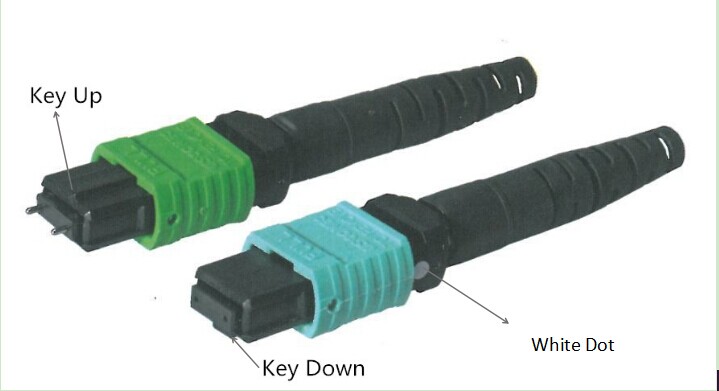
Before looking at each method in detail, it’s necessary to know MPO/MTP connectors. The following will introduce MTP connector. Each MTP connector has a key on one side of the connector body. When the key sits on top, it means the key up position. In this orientation, each of the fiber holes in the connector is numbered in sequence from left to right. We will refer to these connector holes as positions, or P1, P2, etc,. There is also a white dot marked on the right connector body to designate the position P1 of the connector when it’s plugged in.
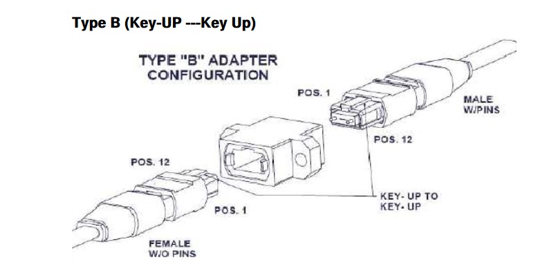
MTP adaptor is designed to hold the two MTPs. As each MTP has a key, there are two types of MTP adaptors (as shown in the following figure):
Type A—key-up to key-down. Here the key is up on one side and down on the other. The two connectors are connected turned 180° in relation to each other;
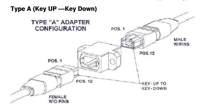
Type B—key-up to key-up. Here both keys are up. The two connectors are connected while in the same position in relation to each other.
- Method A—The transmit‐receive flip must happen in the patch cords, and the trunk cable is a straight through transmission, with the key up on one end, and the key down on the opposite end. This means that the fiber at Position 1 (P1) of the connector on the left will arrive at P1 of other connector.
- Method B—The keys are in an up position at both ends of the trunk cable, but the fiber at P1 in one connector end is at P12 at the opposite end, and the fiber at P12 at the originating end is at position 1 at the opposing end. The fiber positions of Type B cable are reversed at each end.
- Method C—This method uses key up to key down adapters to connect array connector. Each adjacent pair of fibers at one end are flipped at the other end.
40G/100G Transmission Connectivity
40G needs an MPO 12 fiber connector. Only 8 fibers of the 12 are applied with other 4 remaining dark. Four positions are used to transmit, the other four positions are used to receive. 100G requires the use of an MPO 24 fiber connector. The 100G is split into 10 x 10G channels, 10 for transmitting and 10 for receiving.
To upgrade to 40G/100G data transmissions, network designers should better understand well the MPO/MTP polarity. Select the right types of MPO cables, MPO connectors, MPO cassette and patch cables, the proper solution for data centers would be achieved with high density and flexibility and reliability.
Originally published at www.fiber-optic-equipment.com
