Tuesday, November 24, 2015

Fiber Optic Connector Cleaning

With the deployment of 40G and 100G systems in the data center, reliable and efficient fiber installations are critical to the high performance network. Contaminated fiber optic connectors can often lead to degraded performance. Any contamination on the fiber connectors can cause failure of the component or failure of the whole system. So it’s important to keep fiber connectors clean.
Contamination Sources
There are two most important forms of contamination on fiber connectors and they are oils and dust. Oils from human hands will leave a noticeable defect easily seen with a fiberscope. The oil will trap dust against the fiber and bring scratches to the fiber connector. Inserting and removing a fiber can create a small static charge on the ends, which can attract airborne dust particles. Simply removing and re-inserting a fiber may also contaminate the end of the connector with a higher level of dust. Fiber caps, which are used to prevent fiber ends from being contaminated while not seated in a connector, will collect dust, dirt, oil and other contaminants to the fiber when used. Except oil and dust, there also other types of contamination, such as film residues condensed from vapors in the air, powdery coatings leaving after water or other solvents evaporating away. These contaminates tend to more difficult to remove and can also cause damage to equipment if not removed.
Contamination Inspection Tools
To inspect whether a fiber connector is contaminated, one should use fiberscope, clean and resealable container for the endcaps, bulkhead probe. A fiberscope is a customized microscope for inspecting optical fiber components. The fiberscope should provide at least 200x total magnification. The bulkhead probe is a handheld fiberscope used in order to inspect connectors in a bulkhead, backplane, or receptacle port. It should provide at least 200x total magnification displayed on a video monitor.
Contamination Inspection Steps
With contamination inspection tools, you should know how to inspect fiber connectors. The following introduces the inspection steps:
  • Make sure that the lasers are turned off before you begin the inspection. Be careful: Invisible laser radiation might be emitted from disconnected fibers or connectors. Do not stare into beams or view directly with optical instruments.
  • Remove the protective cap and store it in a clean resealable container. Verify the style of connector you inspect and put the appropriate inspection adapter or probe on your equipment.
  • Insert the fiber connector into the fiberscope adapter, and adjust the focus ring so that you see a clear endface image. Or, place the tip of the handheld probe into the bulkhead connector and adjust the focus.
  • On the video monitor, see if there is contamination present on the connector endface (See the following figure).
clean-connector-and-connectors-with-contamination
Connector Cleaning Tools
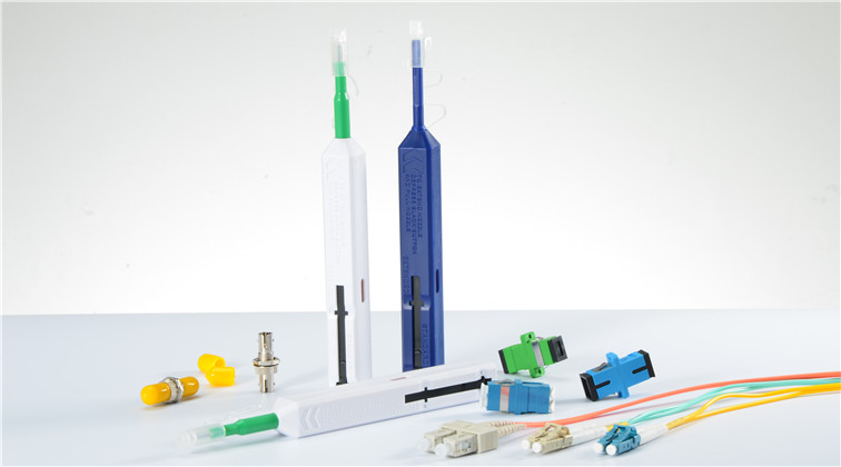
If there is contamination inspected on the fiber connector, then you need to clean it with proper tools. These tools can be divided into four types based on the cleaning method.
fiber-optic-cleaner-one-click
  • Wet cleaning: Optic cleaning with a solvent.
  • Non-Abrasive cleaning: Cleaning without abrasive material touching the fiber optic connector end face.
  • Abrasive cleaning: The popular lint free wipes, such as fiber optic mini foam swabs.
Connector Cleaning Steps
How to clean the fiber connector? Here is about the cleaning steps with abrasive cleaning tools.
  • Gently wipe endface with lint-free pad in one direction.
  • Using a can with compressed gas held upright and approximately 2 inches from the connector end, release a stream of gas on the connector endface for no more than 5 seconds.
  • Gently wipe the ferrule and the end-face surface of the connector with an alcohol pad. Making sure the pad makes full contact with the end-face surface. Wait 5 seconds for the surface to dry.
After finishing the cleaning steps, you should better inspect again to make sure there is definitely no contamination on the connector. Remember never touch the end face of the fiber connector and always install dust caps on unplugged fiber connectors. Do not re-use optic cleaning swabs or lens paper (lint free wipes).
Originally published at www.china-cable-suppliers.com/
Monday, November 16, 2015

Understanding of Optical Losses for Better Data Transmission

When light propagates as a guided wave in a fiber core, it experiences some power losses. These are particularly important for signal transmission through fiber optic cables over long distance. For better telecommunication, we should try to decrease optical losses. Then first we need to know well about optical losses. The article will tell about intrinsic fiber losses and extrinsic fiber losses.
Intrinsic Fiber Losses
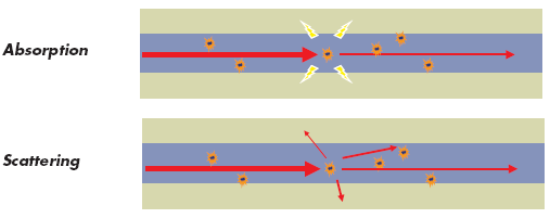
Intrinsic fiber losses are those associated with the fiber optic material itself. There are two kinds: scattering losses and absorption losses (see the following picture). Light is attenuated mainly because of these.
absorption-scattering
  • Absorption Losses Absorption loss is caused by absorption of photons within the fiber such as metal ions (e.g., Cu2+, Fe3+) and hydroxyl (OH–) ions. Optical power is absorbed in the excitation of molecular vibrations of such impurities in the glass. One absorption feature is that it occurs only in the vicinity of definite wavelengths corresponding to the natural oscillation frequencies or their harmonics of the particular material. In modern fibers, absorption losses are almost entirely cuased by OH–1 ions. The fundamental vibration mode of these ions corresponds to l = 2.73 µm and the harmonics at 1.37 and 0.95 µm. To reduce presence of OH1 ions, it’s possible to employ dehydration.
  • Scattering Losses Scattering losses are the second dominat influence factor to the signal attenucation in an optical fiber. This kind of loss is caused by micro variations in the fiber material density, which occur during the manufacturing process. Even though the careful manufacturing techniques is advanced and careful, most fibers are still inhomogeneous with disordered and amorphous structures. The scattering losses decrease in porption to the fourth power of the signal wavelength. So the scattering loss is a dominant loss mechanism below wavelengths of 1,000 nm. It’s also necessary in the third transmission window at the wavelengths of 1,550 nm.
Extrinsic Fiber Losses
These losses are specific to geometry and handling of the fibers and are not functions of the fiber material itself. There are two basic kinds and they are bending losses and connector losses.
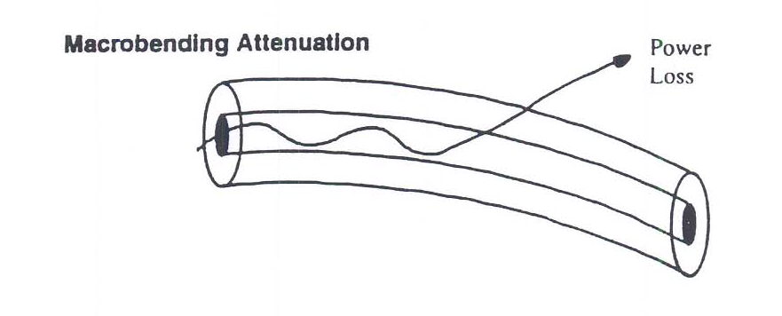
  • Bending Losses When optical fiber cables are bent, they exhibit additional propagation losses. This is called bending losses which is a frequently encountered problem in fiber optics. Typically, these losses rise very quickly once a certain critical bend radius is reached. This critical radius can be very small (a few millimeters) for fibers with robust guiding characteristics (high numerical aperture), or it can be much larger (often tens of centimeters) for single-mode fibers. Losses are greater for bends with smaller radius.bending-attenuation
  • Connector Losses Connector losses are related to the coupling of the output of one fiber with the input of another fiber, or couplings with detectors or other components. The losses may arise in fiber connectors and splices of the joined fibers with cores of different diameters or misaligned centers. Or the losses may occur if fibers’ axes are titled. The losses caused by mismatching of fiber diameters can be approximated by –10 log(d/D). There are other connection losses such as offsets or air gaps between fibers, and poor surface finishes.
From this article, you may know something about optical losses. To get better data transmission, you should consider the above influence factors. For intrinsic fiber losses, the products’ material is critical. For extrinsic fiber losses, note that you should try to avoid bending the fiber and do good coupling of fibers, joining fibers with the same diameters, avoid the fiber axes titled, etc.
Originally published at www.china-cable-suppliers.com/
Tuesday, November 10, 2015

Fiber Optic Splicing

Fiber optic splicing is one of the fiber optic terminations which creates a permanent joint between the two fibers. With the benefits of low light loss and back reflection, fiber optic splicing is a preferred method when the cable runs are too long for a single length of fiber or then joining two different types of cables together. There are two methods of splicing, fusion splicing and mechanical splicing.
Fusion Splicing
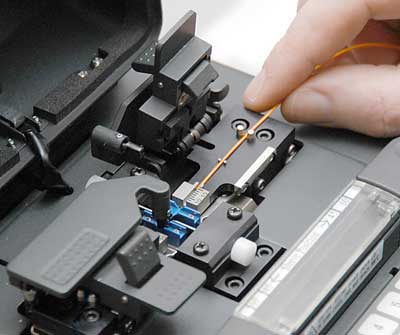
In fusion splicing (as following picture), a machine called fusion splicer is used to precisely align the two fiber ends. Then the glass ends are "fused" or "welded" together using some type of heat or electric arc. This produces a permanent connection between the fibers enabling very low loss light transmission (Typical loss: 0.1 dB). Fusion splicing has the best return loss performance of all the mating and splicing techniques.
fusion-splice
Fusion Splicing Steps
    • Prepare the fiber. Strip the protective coatings, jackets, tubes, strength members, etc. and only leave the bare fiber showing. Please pay attention to keep the fiber clean.
    • Cleave the fiber. Choose a good fiber cleaver. The cleaved end must be mirror-smooth and perpendicular to the fiber axis to obtain a proper splice. But the cleaver is not used to cut the fiber. It’s only used to produce a cleaved end that is as perpendicular as possible.
    • Fuse the fiber. Align the fusion splicer unit and use an electrical arc to melt the fibers, permanently welding the two fiber ends together. Alignment can be manual or automatic.
    • Protect the fiber - To ensure the splice not break during normal handling, you must protect the fiber from bending and tensile forces. A typical fusion splice has a tensile strength between 0.5 and 1.5 lbs and will not break during normal handling but it still requires protection from excessive bending and pulling forces.
Mechanical Splicing
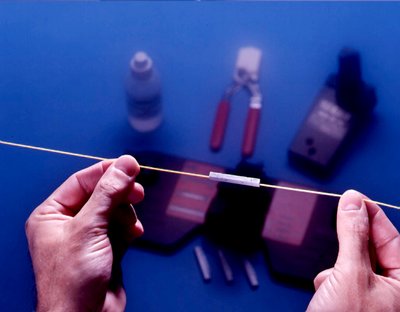
Mechanical splicing (as following picture) aligns and mates the end face of two cleaned and cleaved fiber tip together. It’s a reusable splice. The mechanical splice will have an index matching fluid that eliminates the fiber-to-air interface, there by resulting in less back reflections. Mechanical splices are often used when splices need to be made quickly and easily.
mechanical-splicing
Mechanical Splicing Steps
  • Prepare the fiber. Strip the protective coatings, jackets, tubes, strength members, etc. and only leave the bare fiber showing. Please pay attention to keep the fiber clean.
  • Cleave the fiber. This one is the same to the fusion splicing step. But the cleave precision is as critical.
  • Mechanically join the fibers. This method doesn’t use heat. Simply put the fiber ends together inside the mechanical splice unit. The index matching fluid inside the mechanical splice apparatus will help couple the light from one fiber end to the other. Older apparatus will have an epoxy rather than the index matching fluid holding the cores together.
  • Protect the fiber - the completed mechanical splice provides its own protection for the splice.
Which One Should You Choose?
To decide which fiber splicing method you should choose, you may take two important factors into consideration. First, it’s the cost. Mechanical splicing has a low initial investment ($1,000—$2,000) but costs more per splice ($12-$40 each). While the initial investment is about at least $15,000 and per splice cost is about $0.50 - $1.50. Second, it’s the performance. Fusion splicing offers a high degree performance of lower loss and less back reflection than mechanical splicing.
By the comparison of the cost and performance of two methods, now you know which one is suitable for your applications. If you have enough money and need more precise alignment for lower loss, you could buy a fusion splicing machine. If you just have a small budget and should make a quick splice, then you can choose mechanical fiber optic splice.
Originally published at www.china-cable-suppliers.com/