Monday, October 26, 2015

Passive Optical Network Technology

The tremendous growth in IP traffic badly influenced the access network capacity. It’s believed that the copper-based access networks can’t provide either the minimum bandwidth or the required transmission distance for delivering services of voice, data, and video programs. Passive optical network (PON) is seemed as a promising and cost-effective way to solve this problem.
What’s PON?
PON is a telecommunication network that uses point-to-multipoint fiber to the end-points in which optical splitters are used to enable a single optical fiber to serve multiple end-points. It does not include any electrically powered switching equipment.
Three Devices in PON
There are three distinct devices in the network (as shown in the following picture): the OLT (optical line terminal), the ONUs (optical network units) or ONTs (optical network terminals) and the splitter. Each one has a necessary function in the passive optical network. PON always works under transmission between the OLT and the different ONT’s through optical splitters, which multiplex or demultiplex signals based on their origin and destination.
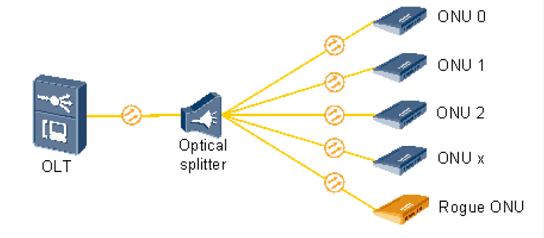
PON-devices
  • OLTs are located in provider’s central switching office. This equipment serves as the point of origination for FTTP (Fiber-to-the-Premises) transmissions coming into and out of the national provider’s network. An OLT, is where the PON cards reside.
  • ONU converts optical signals transmitted via fiber to electrical signals. These electrical signals are then sent to individual subscribers. ONUs are commonly used in fiber-to-the-home (FTTH) or fiber-to-the-curb (FTTC) applications. Using different wavelengths for each service makes it possible to transmit high-speed Internet and video services at the same time. Wavelength multiplexing is performed at the central office and a wavelength demultiplexing mechanism is provided at the customer's house.
  • PON splitter is used to split the fiber optic light into several parts at a certain ratio. For example, a 1X2 50:50 fiber optic splitter will split a fiber optic light beam into two parts, each get 50 percent of the original beam.
Advantages of PON
There are many advantages given by the use of fiber and the passive elements that compose the network. The following will tell about the advantages of PON.
  • High bandwidth The bandwidth allowed by systems based on PON can reach the 10 Gbps rate down to the user. The need to increase the bandwidth and the speed is another justification for the use of PON.
  • Long distance A PON allows for longer distances between central offices and customer premises. While with the Digital Subscriber Line (DSL) the maximum distance between the central office and the customer is only 18000 feet (approximately 5.5 km), a PON local loop can operate at distances of over 20 km.
  • Low cost On one hand, the cost of passive elements is low. On the other hand, the installation of these PON elements is much more economic. And it avoids operation and maintenance costs, such as absence of falls or maintenance of the network feeds.
Of course PON has some disadvantages. Compared with an active optical network, it has less range. That means subscribers must be geographically closer to the central source of the data. PON also make it difficult to isolate a failure when they occur. However, these disadvantages can not avoid choosing PON as the best possible configuration. Because it saves the cost of deploying PON networks regarding other two configurations (point to point and active optical network). And the flexibility of the network allows the usage of a channel by a large number of users.
Originally published at www.china-cable-suppliers.com/
Wednesday, October 21, 2015

How to Terminate Fiber Optic Cables?

Since the late 1970s, various connectors and termination methods have been brought to market. Now in the common case, cables are terminated in two ways: use connectors to make two fibers jointed or to connect the fiber to other network gears; use splices to make a permanent joint between two fibers. And for the former method, you may have little confusions to deal with it. So today this paper will teach you how to terminate by taking an example of fiber optic cable using epoxy.
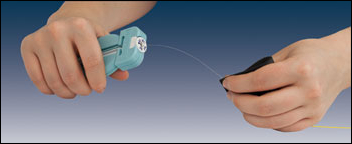
First and foremost, use a proper fiber stripper to carefully slide the jacket off of the fiber to a bare fiber. When you are doing this, be careful that try to avoid breaking the fragile glass fiber. After that, mix the epoxy resin and hardener together and load it into a syringe (If you use the pre-loaded epoxy syringes that are premixed and kept frozen until use, then you don’t do that). And next you must inject the epoxy from the syringe directly into the connector ferrule.
Fiber Stripping Tool
Once you have well prepared the epoxy for your connector, you can insert the fiber cable gently into the terminus inside the connector wall and make the bare fiber core stick out about a half an inch from the front of the ferrule. In the case that your cable is jacketed, you may need a crimping tool, such as Sunkit Modular Crimping Tool, to secure the connector to the jacket and strength the cables. Usually two crimp tools would be perfect to this operation.
Next, you can just wait the epoxy to cure. During this process, in order to make sure the end of the fiber is not damaged while curing, you should place the connected end in a curing holder. And when this is done, just place the cable and curing holder into a curing oven. But you may worry about “wicking” while curing with a conventional oven. All you have to do to avoid that is to make the end face down, which can ensure the epoxy does not come out of the back side of the connector and compromise the strength member of the cable. Remember: your epoxy curing must in accurate times and temperatures.
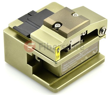
After the epoxy cured sufficiently, fiber cleaver tools will be in use to cleave the excess protruding fiber core so that it could make the fiber close as much as possible to the ferrule tip in case of fiber twisting. Once cleaved, you have to dispose of the fiber clipping. There is a point you should think highly of that you must use a regular piece of tape to retain your fiber debris, or they will easily end up in your skin or even in your eyes or respiratory system.
High Precision Fiber Optic Cleaver
When you finished the fiber cleaved work, you could need fiber polishing tool to remove the excess epoxy from the ferrule tip and buff out any imperfections on the surface of the fiber. A smooth fiber surface can help to reduce the loss of the light. Last, if you have done all the above work, you may move on to the cleaning of the ferrule and fiber tip. After that, the whole termination procedure is done.
If you want to terminate your fiber optic cables by hands, you can follow the above steps. But before you get down to it, you must prepare the tools first that I have mentioned in this paper. All these tools can be found in Fiberstore with good quality and low price. In addition, Fiberstore also can provide the termination tool kits that may be helpful to you. For more details, you could visit www.fs.com.
Article source: http://www.chinacablesbuy.com/how-to-terminate-fiber-optic-cables.html

Tuesday, October 13, 2015

Cable Options for LANs and Data Centers

As the system bandwidth increases, local area network (LAN) campus and building backbones as well as data center backbones are migrating to higher cabled fiber counts. Cable options like loose-tube cable and tight-buffered cable appear for the applications. Later ribbon cable come into the market to meet this need, as they provide the highest fiber density relative to cable size, maximize use of pathway and spaces, and facilitate ease of termination. The following will talk about these kinds of cables.
Loose-tube Cable
Loose-tube cable allows the fibers to lie freely within dry buffered tubes inside the jacket. Because the fibers are loose and not bonded in a ribbon matrix, they do not exhibit any preferential bend and can be flexed in any direction with significantly reduced risk of damage relative to the ribbon cables. Loose-tube cables are much more flexible over the tight bends in the concentrated pathways found in the data center environment.
Loose-tube cable is an design for the LAN applications especially when there are hash environment conditions in outdoors. Many loose-tube cables contain a water resistant gel surrounding the fibers. The gel is good to protect the fibers from moisture, making the cables ideal for high humidity environments. It also enables cable to expand or contract with temperature changes. Loose-tube cable protect the fibers from outside environmental and mechanical damages. That’s why loose-tube cables are widely used in outdoor environments.
Tight-buffered Cable
Meanwhile, there are tight-buffered cables for indoor use. Compared with loose-tube cables, they are better suited for moderate length LAN or WAN connections. Tight-buffered cables offer flexibility, direct connectability and design versatility necessary to satisfy the diverse requirements existing in high performance fiber optic applications.
Instead of using the gel layer, tight-buffered cables have a two-layer coating, plastic and waterproof acrylate. The acrylate keeps moisture away from the cable. Tight-buffered cables are easier to install, because there is no gel to clean up and it does not require a fan out kit for splicing or termination.
Tight-buffered-Cable
Ribbon Cable
This cable is called ribbon cable because of the looks. It contains a lot of conduction wires lined up side-by-side, to create flat, wide cabling, which resembles a ribbon. The cable design characteristically consists of 12 to 216 fibers organized inside a central tube. It can provide the highest fiber density relative to cable size, maximize use of pathway and spaces, and facilitate ease of termination. Ribbon cables are ideal for situations where space is a factor because they lay flat and take up very little room. This kind of cables have emerged as a primary cable choice for deployment in campus, building, and data-center backbone applications where fiber counts of more than 24 are required.
But the 12-fiber ribbon field terminations was limited. So the innovations such as ribbon-splitting tools, ribbon-furcation kits, and field-installable 12-fiber array connectors were introduce. Then 12-fiber ribbons can be easily terminated with simplex and duplex connectors (such as LC or SC type) or with the MTP array connector. The MTP connector is a 12-fiber push/pull optical connector with a footprint similar to the SC simplex connector. These high-density connectors are used to significantly accelerate the network cabling process, minimize errors, and reduce congestion in patch panels. MTP connectorized ribbon cables allow installers to reduce installation time, minimize clutter and maximize the rack space.
ribbon-cable
All in all, it’s very essential to maximize the use of pathway and spaces, especially in campus and data center backbones. The above cables such as loose-tube cable, tight-buffered cable and ribbon cable play obvious roles for space savings. Fiberstore offers all of these cables and each one has different types of cables. There are also customized service such as optional fiber counts, cable types and lengths etc. So you must choose appropriate one for your network here.
Originally published at http://www.china-cable-suppliers.com/

Wednesday, October 7, 2015

Fibre Channel Testing Strategies

Fibre Channel Introduction
Fibre Channel (FC) is a high-speed network technology that enterprises rely on to transport data to remote sites and store it for protection against potentially damaging natural and human events. It is designed to meet the many requirements related to the ever increasing demand for high performance information transfer. The goals of Fibre Channel are to develop practical, inexpensive, yet expendable means of quickly transferring data between workstations, mainframes, supercomputers, storage devices, displays, desktop computers and other peripherials. Although being called Fibre Channel, its architecture does not represent neither a channel nor a real network topology. It allows for an active intelligent interconnection scheme, called a Fabric, to connect devices. The purpose of the Fibre Channel port is to manage a simple point-to-point connection between itself and the Fabric.
Why Test Fibre Channel?
Fibre Channel aims to carry different types of traffic for applications that require first-rate capabilities of storage. The principal trait of Fibre Channel is the fusion of the network technologies, which allows the communications to have some attributes including high bandwidth, low latency, high data integrity, high connectivity, and large distances, etc. Because of its stringent performance requirements, Fibre Channel requires extensive testing during deployment in order to assure the desired service level.
Fibre Channel Testing Strategies
There are three basic types of test instrument apparatus useful in testing Fibre Channel system. They are two-channel pass-through protocol analyzers, data or pattern generators, or emulators.
The two-channel pass-through protocol analyzer is useful in debugging the correctness of the Fibre Channel transport protocol on the physical links as well as assisting in debugging the user applications running on the link. Besides, it is able to be used to stream data to secondary storage for post run analysis. A pattern generator is able to stress the link’s ability to handle data, send legal and illegal user application data, and perform illegal Fibre Channel operations. Building onto the data generator the ability to respond to link inputs in real-time makes a useful tool for hosting applications under test or for emulating systems to other Devices-Under-Test (DUT). In short, this “emulator” can provide a complete, flexible lab environment in which to stimulate and test a DUT.
In addition to the above testing strategies, there is still another issue to be considered, that is, Fibre Channel should be tested with or without the patch cords? To answer this question, the following factors should be clear first.
As a matter of fact, the main deciding factor for whether to test the Fibre Channel with the patch cords included or to just test the permanent links depends on the specification offered by the end user or their consultant. If needed, the Fibre Channel should be tested with the patch cords. Afterwards, if the question is still unclear after checking the specification, you can consider the fact that patch cords are factory terminated and offer a lower risk of defect and errors. Installing permanent link has much more impact on the performance and insertion loss of the Fibre Channel. Sometimes, testing the Fibre Channel with the patch cords is not logistically feasible as the patch cords are not in place during initial testing before active equipment is installed and up and running. The last factor is that typical insertion loss values or maximum insertion loss values are used to design the Fibre Channel or not. If using typical insertion loss, it is important to know how the patch cords impact the Fibre Channel. Even a negligible loss on the patch cords can have an impact on the design and the Fibre Channel performance. If using maximum insertion loss values, patch cords will not have an impact.
After reading the above description, the answer to Fibre Channel testing with or without patch cords is “it depends”. For the other Fibre Channel testing strategies, each has its own features. when you need to test the Fibre Channel, make clear each strategy and then make the correct decision to maximize your network performance.
Originally published at www.fiber-optic-components.com/