Friday, September 25, 2015

Introduction to Fiber Media Converter

Network complexity and the increasing number of devices on the network are driving higher bandwidth requirements and faster network speeds, as well as forcing longer distance requirements within the local area network (LAN). How to deal with these issues? Media converters present solutions to these issues by providing seamless integration of copper and fiber and different fiber types in enterprise LAN networks. Moreover, media converters can support various protocols, data transfer rates and media types to create a more reliable and cost-effective network. There are many different types of media converters, such as fiber media converters, PoE (Power-over-Ethernet) media converters, etc. This article will mainly introduce fiber media converter.
Fiber Media Converter Overview
A fiber media converter is a simple networking device that makes it possible to connect two dissimilar media types such as twisted pair with fiber optic cabling. Fiber media converters play an important role in interconnecting fiber optic cabling-based systems with existing copper-based, structured cabling systems. They can be divided into fiber-to-fiber media converters and copper-to-fiber media converters. For fiber-to-fiber conversion, the multimode fiber to single-mode fiber and a dual fiber link to single fiber can be converted by using bi-directional data flow, while for copper-to-fiber conversion, the electrical signals used in copper unshielded twisted pair (UTP) network cabling are converted into light waves used in fiber optic cabling.
Fiber-to-Fiber Media Converter
Fiber-to-fiber media converters are capable of connecting different fiber optic networks and supporting conversion from one wavelength to another. They can provide connectivity between single-mode and multimode fiber, as well as between dual fiber and single fiber. Normally, fiber-to-fiber media converters are protocol independent and available for Ethernet and TDM (time division multiplexing) applications.
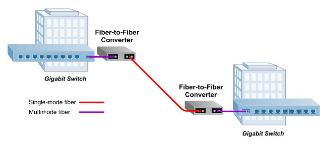
As is shown in the following picture, a fiber-to-fiber media converter is able to extend a multimode network across single-mode fiber with transmission distance up to 140 km. In this application, two Gigabit Ethernet switches equipped with multimode fiber ports are connected by using a pair of Gigabit fiber-to-fiber media converters, which convert the multimode fiber to single-mode and enable the long distance connection between the switches.
fiber-to-fiber media converter

Copper-to-Fiber Media Converter
Copper-to-fiber media converters integrate fiber into a copper infrastructure and make it possible to migrate a local network to fiber while extending the productive life of existing infrastructure. Moreover, they provide connectivity for Ethernet, Fast Ethernet, Gigabit and 10 Gigabit Ethernet devices. Also, they are able to perform 10/100, or 10/100/1000 rate switching and enable the integration of equipment with different data transfer rates and interface types into one seamless network.
As can be seen from the following diagram, 10/100 media converters are installed in a redundant power chassis for high-density fiber distribution from UTP switch equipment (A) at the network core. A UTP workgroup switch (B) is connected via fiber to the network core with a standalone 10/100 media converter. Another 10/100 converter enables fiber connectivity to PU UTP port in a fiber-to-desktop application (C). An Ethernet switch (D) is connected directly via fiber to the media converter module at the network core.
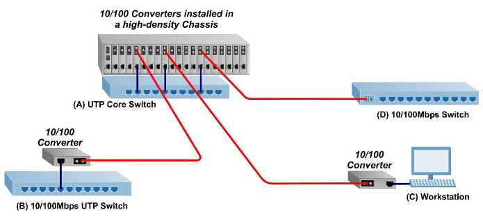
copper-to-fiber media converter

To sum up, fiber-to-fiber media converters are ideal solutions for the conversion between multimode and single-mode fibers and then increase the transmission distance. Copper-to-fiber media converters are simple and inexpensive solutions for matching copper ports to fiber infrastructure. Fiber media converters are flexible and cost-effective devices for implementing and optimizing fiber links in all types of networks. Fiberstore has various fiber media converters. It is an excellent choice for you.
Originally published at www.fiber-optic-components.com/

Friday, September 18, 2015

40 Gigabit Ethernet Solution


40 Gigabit Ethernet is a standard that enables the transfer of Ethernet frames at speeds of up to 40 gigabits per second (Gbps), allowing 40 Gigabit Ethernet-enabled equipment to handle traffic at the aggregation and core layers. It satisfies the greater demands for faster data transmission and higher bandwidths. Thus, the business case for 40 Gigabit Ethernet is becoming inescapably compelling although 10 Gigabit Ethernet is still making its way into data center. A right and cost-effective solution for 40 Gigabit Ethernet is very necessary for all users who want to migrate to 40 Gigabit Ethernet.
40 Gigabit Ethernet Solution
The picture above is the summary about 40 Gigabit Ethernet, explaining significantly that cables and transceivers are the basis of the whole solution. And actually, they are also the main cost of the item. Next some types of 40 Gigabit Ethernet cables and 40 Gigabit Ethernet transceivers will be introduced in details.
40 Gigabit Ethernet Cables
The cable applied in 40 Gigabit Ethernet can be optical fiber or copper cable. The copper cable for 40 Gigabit Ethernet is designed for short reach, up to at least 7 m. As to optical cable, there are two types: singlemode cable and multimode cable. The transmission distance of multimode cable for 40 Gigabit Ethernet can be up to 150 m, which is much shorter than the transmission distance of singlemode cable (It can be up to 10 km). Generally, the common used types are OM3 and OM4 multimode cables in that its reach supports a wider range of deployment configurations compared to copper solutions, and the cost is lower compared to singlemode solutions.
What is more, the MPO (Multi-Fiber Push On)/MTP (Multi-fiber Termination Push-on) cable is considered the best solution for 40GbE. It can connect the multimode transceivers to support the multifiber parallel optics channels. For 40 Gigabit Ethernet, we can use 8 fibers MPO/MTP harness cables or 12 fibers MPO/MTP trunk cables. The former is to directly connect a QSFP port to other 4 SFP+ ports. The latter is to directly connect one QSFP port to another QSFP port. Here is a picture to help you know it clearly.
MTP Cable
40 Gigabit Ethernet Transceivers
According to different standard form factors, 40 Gigabit Ethernet transceivers can be divided into different types, such as CFP transceiver, CXP transceiver and QSFP transceiver, ect.
CFP transceiver, which has 12 transmit and 12 receive 10-Gbps lanes, can support one 100 Gigabit Ethernet port, or up to three 40 Gigabit Ethernet ports. This module is used for 40GBASE-SR4, 40GBASE-LR4. The former is based on 850nm technology and supports transmission over at least 100m OM3 parallel fibers and at least 150m OM4 parallel fibers, while the latter is based on 1310nm , coarse wave division multiplexing (CWDM) technology and supports transmission over at least 10km on singlemode fiber.
CXP transceiver also has 12 transmit and 12 receive 10-Gbps lanes as well as CFP transceiver, supporting one 100 Gigabit Ethernet port or up to three 40 Gigabit Ethernet ports. Compared with CFP transceiver, the size of it is much smaller. And it is mainly designed for the high-density requirements of the data center, serving the needs of multimode optics and copper.
QSFP transceiver provides four transmit and four receive lanes to support 40 Gigabit Ethernet applications for multimode fiber and copper today. The size of it is the same with CXP transceiver. It is mainly designed to support Serial Attached SCSI, 40G Ethernet, PCIe, 20G/40G Infiniband, and other communications standards.
Fiberstore 40 Gigabit Ethernet Solution
Fiberstore can offer customers 40 Gigabit Ethernet connectivity options for data center networking, enterprise core aggregation, and service provider transport applications. Since the products are all in good quality and low price, it may be the best choice for you to deploy the network.
Originally published at http://www.chinacablesbuy.com/

DAC – Direct Attach Cables

Nowadays, more bandwidth is needed to meet the requirements of increasing data transmission between the servers and switches. Then many network equipment such as direct attach cable are designed to provide more bandwidth.
Direct attach cable, short for DAC, is a form of cable terminated with transceiver modules on each end. It’s widely applied in storage area network, data center, and high-performance computing connectivity, etc. It’s a cost-effective, low power consumption and low latency solution which is ideal for high-density.
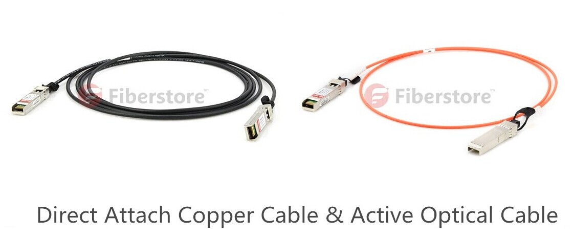
DAC can be divided into several categories according to different standards. First, based on the connector type, manufactures like Fiberstore provide 10G SFP+ direct attach cables, 40G QSFP+ direct attach cables and 120G CXP AOC (Active Optical Cable). Second, DAC can be classified into active and passive versions. Third, DAC are made of the two kinds of cable materials including copper and optical fiber. They are respectively called direct attach copper cable and active optical cable. (As shown in the following picture)
Direct-Attach-Cable
  • Connector
    Why are there different connector types? Because Direct attach cables with different connectors can support different data rate applications, such as 10GbE, 40GbE... SFP+ cables with enhanced SFP connectors are designed to work with equipment with 10G SFP+ interface. SFP+ cables provide high performance in 10 GbE network applications. QSFP+ cables are applied in high speed network backbones, enterprise network switching and network storage. QSFP+ cables are used for 40GbE and Infniband standards, to maximize performance. 120G CXP AOCs integrates the design of 12-Channel VCSEL array and PIN array, providing 12 parallel data channels. Each channel can support up to 10.5Gbps transmission data rate, total 126Gbps bandwidth.
  • Active & Passive
    Both active and passive direct attach cables are available in the market now. If signals process electronics in the transceiver modules to improve signal quality for a longer cable distance, the direct attach cable assembly is considered to be active. While if there are no signal processing electronics in the transceiver modules just for a short distance, the direct attach cable assembly is passive. Their big difference is about the data transmission distance.
  • Cable Material
    What’s the differences between direct attach copper cable and active optical cable? Direct attach copper cable is good for handling high bandwidth transmission within short distance. But it’s difficult to be managed because the cable material is heavy and bulky. Besides, the nature of electrical signals makes the direct attach copper cable vulnerable to the effects of electromagnetic interference (EMI), such as undesirable responses, degradation, or complete system failure. On the contrary, AOC weighs less and can support longer transmission distance. It’s immune to electromagnetic energy since the optical fiber is dielectric (not able to conduct electric current). What’s more, it is an alternative to optical transceivers and it can eliminate the separable interface between transceiver module and optical cable. However, it costs more than copper cable.
Direct attach cables provide good performance in high speed applications in storage, networking and telecommunication. Direct attach cables can also save cost and power in short reach applications because they use the same port as an optical transceiver. It’s certain that the products will continuously evolve to meet consumers’ needs of higher data rates with lower power consumption and cost.
Originally published at http://www.china-cable-suppliers.com/

Friday, September 4, 2015

Knowledge About ROADM

Over the past decades, the use of bandwidth in transport networks increases dramatically. This resulted in the generation of wave division multiplexing (WDM) which could introduce more bandwidths on a single fiber. The need for more bandwidth flexibilities, operational efficiencies, and technology advances brought the optical add/drop multiplexer (OADM) to add or drop wavelengths at a node point. FOADM, an initial type of OADM, which uses fixed lasers for fixed wavelengths has emerged. But it can’t meet the needs of bandwidth. So this drives the emergence of the other kind of OADM – ROADM.
ROADM (reconfigurable optical add/drop multiplexer) adds the ability to remotely switch traffic from a WDM system at the wavelength layer. It avoids the unnecessary optical-electrical-optical conversion. And it’s bit-rate/protocol transparent, so future upgrades of bit-rate/protocol can be accommodated without upgrading the switch. ROADM technology has revolutionized optical network and offered huge bandwidth for data transport.
ROADM is an integral part of WDM networks due to its advantages. ROADM allows for remote configuration and reconfiguration. The planning of entire bandwidth assignment does not need to be carried out during initial deployment of a system. The configuration can be done as required without affecting traffic already passing the ROADM. It provides full flexibility of delivering any wavelength to any node throughout the ring infrastructure. It automates the optical layer to remove error-prone service provisioning, and equalizes signal loss across all wavelengths, reducing the need for expensive signal boosting equipment. What’s more, it can reduce the costs of networks.
ROADM functionality firstly appeared in long-haul equipment. By 2005, it started to appear in metro optical systems because of the network traffic driven by the increasing demand for packet-based services such as Ethernet, high-speed data, audio and video services. ROADM equipment is used to build a versatile, agile and quickly provisioned optical transport network. This transport network can scale in both distance and number of nodes.
As the continuous development of technology, it brings three generations of ROADM. The 1st generation was to solve fiber exhaust problems caused by inflexibility in the long haul networks. Compared with the 1st generation, the 2nd generation ROADM is typified by wavelength blocker technology. And the structure design of the 2nd generation is simple with a tap (a splitter and filter array) used to drop any number of selected wavelengths. But if all wavelengths enter the blocker, the pass-through wavelengths will not be blocked. The 3rd generation is the wavelength selective switch (WSS) (see the following picture). It’s more versatile, smaller, consuming less power and cheaper than 2nd generation ROADM.
WSS ROADM
Common advantages of ROADM like automatic performance monitoring and equalization make WDM systems more useful. However, the current ROADM technology is not perfect and still needs to be upgraded. The development of the advanced ROADM depends on the growth of supporting optical components maturity, progress of integrated optics technology, improved capability of the equipment and new algorithms. Whatever, the new design should concern those factors such as the future broadband communication network service needs, fewer components, fewer devices in network, effective interoperability and the flawless service evolution with considerable decrease in the operational costs.
Originally published at http://www.china-cable-suppliers.com/