Monday, December 28, 2015

EPON vs. GPON—Which Will Be More Popular?

With the development of passive optical networking (PON) technology, two PON standards are striking in FTTH solution area and they are Ethernet passive optical networking (EPON) and ATM (asynchronous transfer mode)-based Gigabit passive optical networking (GPON). During these years, it has become a hot topic that which will be more popular in broadband access and optical telecom applications, EPON or GPON? This article will compare these two technologies from the differences of architecture, bandwidth, efficiency, cost, etc.
Architecture
The biggest difference between the two technologies shows in architecture. EPON employs a single Layers 2 network that uses IP to carry data, voice, and video. While GPON provides three Layer 2 networks: ATM for voice, Ethernet for data, and proprietary encapsulation for voice.
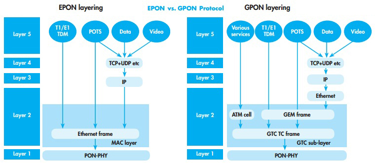
EPON-and-GPON
EPON provides seamless connectivity for any type of IP-based or other "packetized" "communications". Since Ethernet devices are so popular and easy to get, implementation of EPONs can be highly cost-effective.
In GPON, virtual circuits are provisioned for different kinds of services sent from a central office primarily to business end users. This kind of transport provides high-quality service, but includes significant overhead because virtual circuits should be provisioned for each type of service. GPON equipment requires multiple protocol conversions, segmentation and reassembly (SAR), virtual channel (VC) termination and point-to-point protocol (PPP).
Bandwidth
EPON delivers symmetrical bandwidth of 1 Gbit/s. EPON's Gigabit Ethernet service actually constitutes 1 Gbit/s of bandwidth for data and 250 Mbit/s of bandwidth for encoding. GPON promises 1.25-Gbit/s or 2.5-Gbit/s downstream, and upstream bandwidths scalable from 155 Mbit/s to 2.5 Gbit/s. GPON's 1.25-Gbit service specifies a usable bandwidth of 1.25 Gbit/s, with no requirement for encoding. Gigabit Ethernet interfaces to the aggregation switch, central office, and metro are currently cost-effective to aggregate 1-Gbit ports for transport. But for 1.25 Gbit, there is no way.
Efficiency
Efficiency has to be considered in both directions of a PON. Each PON protocol introduces its own overhead in either direction. In the downstream direction, protocol overhead could be negligible. In the upstream direction, the total scheduling overhead within EPON is from 90.33 percent to 97.08 percent compared to a GbE point-to-point link. In the downstream direction, EPON efficiency reaches from 97.13 percent to 98.92 percent of the efficiency of a point-to-point 1GbE link, while GPON in GTC Encapsulation Method (GEM) mode can achieve ~ 95 percent efficiency of its usable bandwidth. The downstream EPON data rate can be doubled to 2.5Gbps comparable to GPON.
Cost
EPON simplifies the networks and needs no complex and expensive ATM and Sonet elements. Thus it helps lower the costs to subscribers. Now the cost of EPON equipment is about 10 percent of the costs of GPON equipment.
Encryption
Encryption is part of the ITU standard. EPON uses an AES-based mechanism, which is supported by multiple silicon vendors and deployed in the field. And EPON encryption is both downstream and upstream. However, GPON encryption is downstream only.
Ethernet Features
EPON is an IEEE Ethernet standard and uses Ethernet switches within its silicon, it can natively support all of the 802.1 and 802.3 Ethernet, including VLAN tags, prioritization, OAM, etc. All Ethernet services can be natively delivered in a manner identical to what is done with switched Ethernet today. As to GPON, it only defines the transport of Ethernet frames. So it has no native Ethernet functionality. Ethernet switches must be placed either in front of or within GPON OLTs and ONTs to provide any additional Ethernet capabilities.
EPON and GPON technologies have been introduced into the market because of service quality and price point. By comparing the differences of the two technologies, it shows EPON is a superior technology for delivering residential and small-to-medium enterprise Ethernet services in terms of its advantages in bandwidth, efficiency, cost, encryption and Ethernet features. So EPON will be employed in FTTH solution area in a large scale earlier and faster than GPON.
Originally published at http://www.streetarticles.com/internet-and-businesses-online/epon-vs-gponwhich-will-be-more-popular
Tuesday, December 15, 2015

EPON — An Ideal Optical Access Network Solution

In recent years, the telecommunications backbone has experienced huge growth. The tremendous growth of Internet traffic has far surpassed the network capacity. The “last mile” still remains the bottle neck between high-capacity local area networks and the backbone network. So a new technology for optical access network, which is simple, scalable but not expensive, is needed. And that is Ethernet passive optical network (EPON).
EPON Definition
EPON, unlike other PON technologies which are based on the ATM standard, is based on the Ethernet standard. This lets you utilize the economies-of-scale of Ethernet, and provides simple, easy-to-manage connectivity to Ethernet-based, IP equipment, both at the customer premises and at the central office. As with other Gigabit Ethernet media, it is well-suited to carry packetized traffic, which is dominant at the access layer, as well as time-sensitive voice and video traffic.
EPON Network
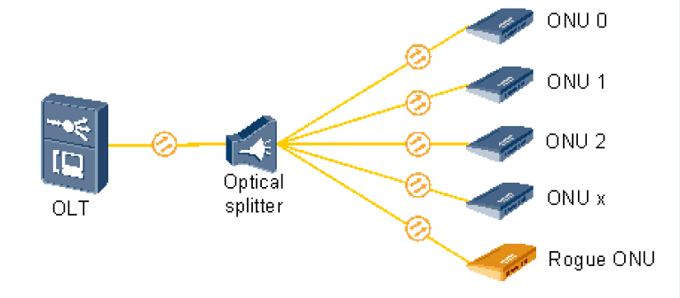
An EPON network includes two parts: an optical line terminal (OLT) and an optical network unit (ONU).
The OLT resides in the central office (CO). This could typically be an Ethernet switch or Media Converter platform. OLT is mainly designed for controlling the information float across the optical distribution network (ODN). OLT has two float directions: upstream (getting an distributing different type of data and voice traffic from users) and downstream (getting data, voice and video traffic from metro network or from a long-haul network and sending it to all ONU modules on the ODN.
The ONU resides at or near the customer premise, in a building, or on the curb outside. It uses optical fiber for connecting to the PON on the one side, while interfacing with customers on the other side.
EPON Upstream and Downstream Traffic
In an EPON, the process of transmitting data downstream from the OLT to multiple ONU is fundamentally different from transmitting data upstream from multiple ONUs to the OLT.
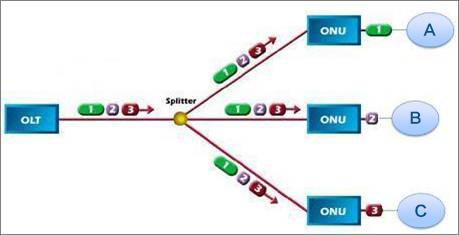
In the downstream direction (from network to user), Ethernet frames transmitted by OLT pass through a 1:N (N represents the number of subscribers each fiber can serve) passive splitter and reach each ONU. Splitting ratios are usually between 4 and 64. At the splitter, the traffic is divided into separate signals, each carrying all of the ONU–specific packets. When the data reaches the ONU, it accepts the packets that are intended for it and discards the packets that are intended for other ONUs.
downsteam
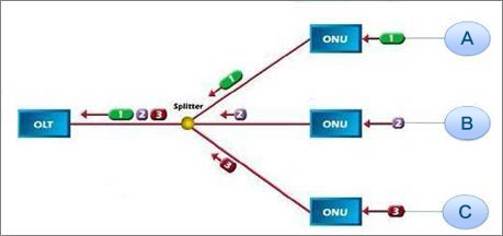
In the upstream direction (from user to network ), due to the directional properties of a passive combiner (optical splitter), data frames from any ONU will only reach the OLT, not other ONUs. Frames in EPON from different ONUs transmitted simultaneously may collide. Thus, ONUs need to share the trunk fiber channel capacity and resources.
upstream
EPON Advantages
First, EPON uses a point-to-multipoint topology instead of point--to-point in the outside plant. Thus it saves much of the cost of running fiber from every customer to the CO, installing active electronics at both ends of each fiber and managing all of the fiber connections at the CO. And EPON also eliminates active electronic components, such as regenerators and amplifiers, and replaces them with passive optical couplers that are less-expensive, simpler, and longer lived than active ones. As to the cost of expensive electronic components and lasers in the OLT, it will be shared over many subscribers not paid by each subscriber.
Second, EPON offers high bandwidth to subscriber. The traffic rates of 1Gbps in downstream and return traffic of 800 Mbps have been achieved already. Compared with point--to-point technology, EPON is specially made to address the unique demands of the access work. So more bandwidth can be got by each subscriber.
At last, the main advantage of EPON is that it can eliminate complex and expensive asynchronous transfer mode (ATM) and SONET elements and simplify the networks dramatically. Traditional telecom networks use a complex and multilayered architecture. While this architecture requires a router network to carry IP traffic, ATM switches to create virtual circuits, add/drop multiplexers (ADM) and digital cross-connects to manage SONET rings, and point-to-point DWDM optical links.
Summary
EPON is suitable for Fiber-to-the-Home/Building/Business applications, including voice, data and video services. EPON is a shared network but with much higher bandwidth. It’s a highly attractive access solution for service providers to extend fiber into the last mile because of low cost and good performance, resulting from their nature as passive networks, point-to-multipoint architecture, and native Ethernet protocol.

Originally published at www.fiber-optic-equipment.com

Tuesday, December 8, 2015

Which One Will You Choose for FTTx? PON or AON?

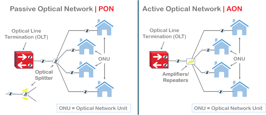
When it comes to FTTx deployment, there are two competing network solutions which are PON (Passive Optical Network) and AON (Active Optical Network). What is the difference between them? And which one will you choose? PON or AON? You may find the answer from the following contents.
PON-AON
PON
A PON consists of an optical line terminator (OLT) located at the Central Office (CO) and a set of associated optical network terminals (ONT) to terminate the fiber–usually located at the customer’s premise. Both devices require power. Instead of using powered electronics in the outside plant, PON uses passive splitters and couplers to divide up the bandwidth among the end users–typically 32 over a maximum distance of 10-20km.
AON
An active optical system uses electrically powered switching equipment to manage signal distribution and direct signals to specific customers. This switch opens and closes in various ways to direct the incoming and outgoing signals to the proper place. Thus, a subscriber can have a dedicated fiber running to his or her house. Active networks can serve a virtually unlimited number of subscribers over an 80km distance.
Advantages and Disadvantages of PON
  • Advantages PON has some distinct advantages. It’s efficient, in that each fiber optic strand can serve up to 32 users. Compared to AON, PON has a lower building cost and lower maintenance costs. Because there are few moving or electrical parts and things don’t easily go wrong in a PON.
  • Disadvantages PON also has some disadvantages. One of the biggest disadvantages is that these splitters have no intelligence, and therefore cannot be managed. Then you can’t check for problems cost-effectively when a service outage occurs. Another major disadvantage is its inflexibility. If one needs to re-design the network or pull a new strand of fiber from the upstream splitter, all downstream customers must come offline for changing the splitter in the network. At last, since PONs are shared networks, every subscriber gets the same bandwidth. So data transmission speed may slow down during peak usage times.
Advantages and Disadvantages of AON
  • Advantages AON offers some advantages, as well. First, its reliance on Ethernet technology makes interoperability among vendors easy. Subscribers can select hardware that delivers an appropriate data transmission rate and scale up as their needs increase without having to restructure the network. Second, it’s about the distance. An active network has the distance limitation of 80 km regardless of the number of subscribers being served. At last, there are some other advantages like high flexibility for deploying different services to residential and business customers, and low subscriber cost.
  • Disadvantages Like PON, AON also has its weaknesses. It needs at least one switch aggregator for every 48 subscribers. Because it requires power, AON inherently is less reliable than PON.
From the above contents, you can find that both technologies have its advantages and disadvantages. In some cases, FTTx systems actually combine elements of both passive and active architectures to form a hybrid system. Thus, to decide which technology to deploy, you should consider your own unique circumstances.
Originally published at www.china-cable-suppliers.com/

Tuesday, December 1, 2015

Why Does FTTH Develop So Rapidly?

FTTH (Fiber to the Home) is a form of fiber optic communication delivery in which the optical fiber reached the end users home or office space from the local exchange (service provider). FTTH was first introduced in 1999 and Japan was the first country to launch a major FTTH program. Now the deployment of FTTH is increasing rapidly. There are more than 100 million consumers use direct fiber optic connections worldwide. Why does FTTH develop so rapidly?
FTTH is a reliable and efficient technology which holds many advantages such as high bandwidth, low cost, fast speed and so on. This is why it is so popular with people and develops so rapidly. Now, let’s take a look at its advantages in the following.
FTTH
  • The most important benefit to FTTH is that it delivers high bandwidth and is a reliable and efficient technology. In a network, bandwidth is the ability to carry information. The more bandwidth, the more information can be carried in a given amount of time. Experts from FTTH Council say that FTTH is the only technology to meet consumers’ high bandwidth demands.
  • Even though FTTH can provide the greatly enhanced bandwidth, the cost is not very high. According to the FTTH Council, cable companies spent $84 billion to pass almost 100 million households a decade ago with lower bandwidth and lower reliability. But it costs much less in today’s dollars to wire these households with FTTH technology.
  • FTTH can provide faster connection speeds and larger carrying capacity than twisted pair conductors. For example, a single copper pair conductor can only carry six phone calls, while a single fiber pair can carry more than 2.5 million phone calls simultaneously. More and more companies from different business areas are installing it in thousands of locations all over the world.
  • FTTH is also the only technology that can handle the futuristic internet uses when 3D “holographic” high-definition television and games (products already in use in industry, and on the drawing boards at big consumer electronics firms) will be in everyday use in households around the world. Think 20 to 30 Gigabits per second in a decade. No current technologies can reach this purpose.
  • The FTTH broadband connection will bring about the creation of new products as they open new possibilities for data transmission rate. Just as some items that now may seem very common were not even on the drawing board 5 or 10 years ago, such as mobile video, iPods, HDTV, telemedicine, remote pet monitoring and thousands of other products. FTTH broadband connections will inspire new products and services and could open entire new sectors in the business world, experts at the FTTH Council say.
  • FTTH broadband connections will also allow consumers to “bundle” their communications services. For example, a consumer could receive telephone, video, audio, television and just about any other kind of digital data stream using a simple FTTH broadband connection. This arrangement would more cost-effective and simpler than receiving those services via different lines.
As the demand for broadband capacity continues to grow, it’s likely governments and private developers will do more to bring FTTH broadband connections to more homes. According to a report, Asian countries tend to outpace the rest of the world in FTTH market penetration. Because governments of Asia Pacific countries have made FTTH broadband connections an important strategic consideration in building their infrastructure. South Korea, one of Asian countries, is a world leader with more than 31 percent of its households boasting FTTH broadband connections. Other countries like Japan, the United States, and some western countries are also building their FTTH broadband connections network largely. It’s an inevitable trend that FTTH will continue to grow worldwide.
Originally published at www.china-cable-suppliers.com

Tuesday, November 24, 2015

Fiber Optic Connector Cleaning

With the deployment of 40G and 100G systems in the data center, reliable and efficient fiber installations are critical to the high performance network. Contaminated fiber optic connectors can often lead to degraded performance. Any contamination on the fiber connectors can cause failure of the component or failure of the whole system. So it’s important to keep fiber connectors clean.
Contamination Sources
There are two most important forms of contamination on fiber connectors and they are oils and dust. Oils from human hands will leave a noticeable defect easily seen with a fiberscope. The oil will trap dust against the fiber and bring scratches to the fiber connector. Inserting and removing a fiber can create a small static charge on the ends, which can attract airborne dust particles. Simply removing and re-inserting a fiber may also contaminate the end of the connector with a higher level of dust. Fiber caps, which are used to prevent fiber ends from being contaminated while not seated in a connector, will collect dust, dirt, oil and other contaminants to the fiber when used. Except oil and dust, there also other types of contamination, such as film residues condensed from vapors in the air, powdery coatings leaving after water or other solvents evaporating away. These contaminates tend to more difficult to remove and can also cause damage to equipment if not removed.
Contamination Inspection Tools
To inspect whether a fiber connector is contaminated, one should use fiberscope, clean and resealable container for the endcaps, bulkhead probe. A fiberscope is a customized microscope for inspecting optical fiber components. The fiberscope should provide at least 200x total magnification. The bulkhead probe is a handheld fiberscope used in order to inspect connectors in a bulkhead, backplane, or receptacle port. It should provide at least 200x total magnification displayed on a video monitor.
Contamination Inspection Steps
With contamination inspection tools, you should know how to inspect fiber connectors. The following introduces the inspection steps:
  • Make sure that the lasers are turned off before you begin the inspection. Be careful: Invisible laser radiation might be emitted from disconnected fibers or connectors. Do not stare into beams or view directly with optical instruments.
  • Remove the protective cap and store it in a clean resealable container. Verify the style of connector you inspect and put the appropriate inspection adapter or probe on your equipment.
  • Insert the fiber connector into the fiberscope adapter, and adjust the focus ring so that you see a clear endface image. Or, place the tip of the handheld probe into the bulkhead connector and adjust the focus.
  • On the video monitor, see if there is contamination present on the connector endface (See the following figure).
clean-connector-and-connectors-with-contamination
Connector Cleaning Tools
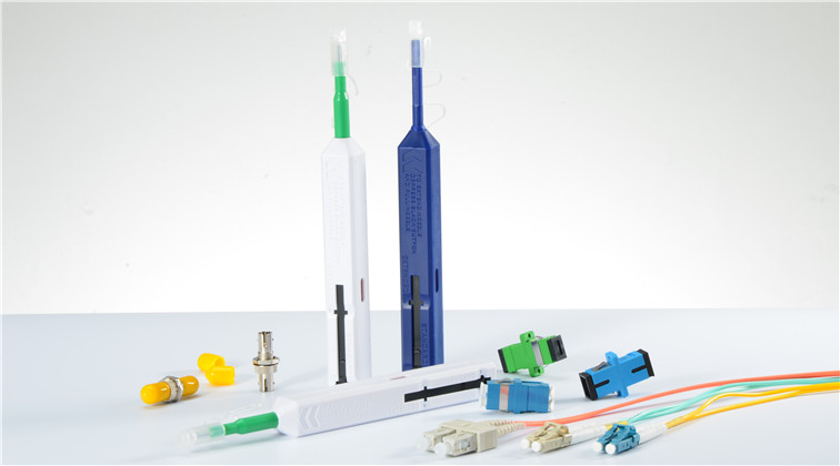
If there is contamination inspected on the fiber connector, then you need to clean it with proper tools. These tools can be divided into four types based on the cleaning method.
fiber-optic-cleaner-one-click
  • Wet cleaning: Optic cleaning with a solvent.
  • Non-Abrasive cleaning: Cleaning without abrasive material touching the fiber optic connector end face.
  • Abrasive cleaning: The popular lint free wipes, such as fiber optic mini foam swabs.
Connector Cleaning Steps
How to clean the fiber connector? Here is about the cleaning steps with abrasive cleaning tools.
  • Gently wipe endface with lint-free pad in one direction.
  • Using a can with compressed gas held upright and approximately 2 inches from the connector end, release a stream of gas on the connector endface for no more than 5 seconds.
  • Gently wipe the ferrule and the end-face surface of the connector with an alcohol pad. Making sure the pad makes full contact with the end-face surface. Wait 5 seconds for the surface to dry.
After finishing the cleaning steps, you should better inspect again to make sure there is definitely no contamination on the connector. Remember never touch the end face of the fiber connector and always install dust caps on unplugged fiber connectors. Do not re-use optic cleaning swabs or lens paper (lint free wipes).
Originally published at www.china-cable-suppliers.com/

Monday, November 16, 2015

Understanding of Optical Losses for Better Data Transmission

When light propagates as a guided wave in a fiber core, it experiences some power losses. These are particularly important for signal transmission through fiber optic cables over long distance. For better telecommunication, we should try to decrease optical losses. Then first we need to know well about optical losses. The article will tell about intrinsic fiber losses and extrinsic fiber losses.
Intrinsic Fiber Losses
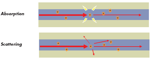
Intrinsic fiber losses are those associated with the fiber optic material itself. There are two kinds: scattering losses and absorption losses (see the following picture). Light is attenuated mainly because of these.
absorption-scattering
  • Absorption Losses Absorption loss is caused by absorption of photons within the fiber such as metal ions (e.g., Cu2+, Fe3+) and hydroxyl (OH–) ions. Optical power is absorbed in the excitation of molecular vibrations of such impurities in the glass. One absorption feature is that it occurs only in the vicinity of definite wavelengths corresponding to the natural oscillation frequencies or their harmonics of the particular material. In modern fibers, absorption losses are almost entirely cuased by OH–1 ions. The fundamental vibration mode of these ions corresponds to l = 2.73 µm and the harmonics at 1.37 and 0.95 µm. To reduce presence of OH1 ions, it’s possible to employ dehydration.
  • Scattering Losses Scattering losses are the second dominat influence factor to the signal attenucation in an optical fiber. This kind of loss is caused by micro variations in the fiber material density, which occur during the manufacturing process. Even though the careful manufacturing techniques is advanced and careful, most fibers are still inhomogeneous with disordered and amorphous structures. The scattering losses decrease in porption to the fourth power of the signal wavelength. So the scattering loss is a dominant loss mechanism below wavelengths of 1,000 nm. It’s also necessary in the third transmission window at the wavelengths of 1,550 nm.
Extrinsic Fiber Losses
These losses are specific to geometry and handling of the fibers and are not functions of the fiber material itself. There are two basic kinds and they are bending losses and connector losses.
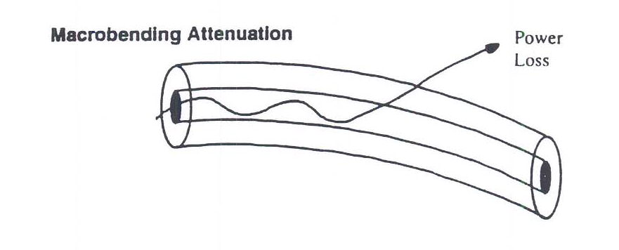
  • Bending Losses When optical fiber cables are bent, they exhibit additional propagation losses. This is called bending losses which is a frequently encountered problem in fiber optics. Typically, these losses rise very quickly once a certain critical bend radius is reached. This critical radius can be very small (a few millimeters) for fibers with robust guiding characteristics (high numerical aperture), or it can be much larger (often tens of centimeters) for single-mode fibers. Losses are greater for bends with smaller radius.bending-attenuation
  • Connector Losses Connector losses are related to the coupling of the output of one fiber with the input of another fiber, or couplings with detectors or other components. The losses may arise in fiber connectors and splices of the joined fibers with cores of different diameters or misaligned centers. Or the losses may occur if fibers’ axes are titled. The losses caused by mismatching of fiber diameters can be approximated by –10 log(d/D). There are other connection losses such as offsets or air gaps between fibers, and poor surface finishes.
From this article, you may know something about optical losses. To get better data transmission, you should consider the above influence factors. For intrinsic fiber losses, the products’ material is critical. For extrinsic fiber losses, note that you should try to avoid bending the fiber and do good coupling of fibers, joining fibers with the same diameters, avoid the fiber axes titled, etc.
Originally published at www.china-cable-suppliers.com/

Tuesday, November 10, 2015

Fiber Optic Splicing

Fiber optic splicing is one of the fiber optic terminations which creates a permanent joint between the two fibers. With the benefits of low light loss and back reflection, fiber optic splicing is a preferred method when the cable runs are too long for a single length of fiber or then joining two different types of cables together. There are two methods of splicing, fusion splicing and mechanical splicing.
Fusion Splicing
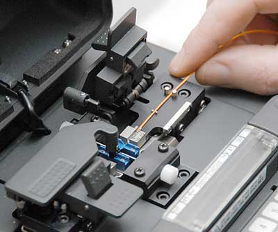
In fusion splicing (as following picture), a machine called fusion splicer is used to precisely align the two fiber ends. Then the glass ends are "fused" or "welded" together using some type of heat or electric arc. This produces a permanent connection between the fibers enabling very low loss light transmission (Typical loss: 0.1 dB). Fusion splicing has the best return loss performance of all the mating and splicing techniques.
fusion-splice
Fusion Splicing Steps
    • Prepare the fiber. Strip the protective coatings, jackets, tubes, strength members, etc. and only leave the bare fiber showing. Please pay attention to keep the fiber clean.
    • Cleave the fiber. Choose a good fiber cleaver. The cleaved end must be mirror-smooth and perpendicular to the fiber axis to obtain a proper splice. But the cleaver is not used to cut the fiber. It’s only used to produce a cleaved end that is as perpendicular as possible.
    • Fuse the fiber. Align the fusion splicer unit and use an electrical arc to melt the fibers, permanently welding the two fiber ends together. Alignment can be manual or automatic.
    • Protect the fiber - To ensure the splice not break during normal handling, you must protect the fiber from bending and tensile forces. A typical fusion splice has a tensile strength between 0.5 and 1.5 lbs and will not break during normal handling but it still requires protection from excessive bending and pulling forces.
Mechanical Splicing
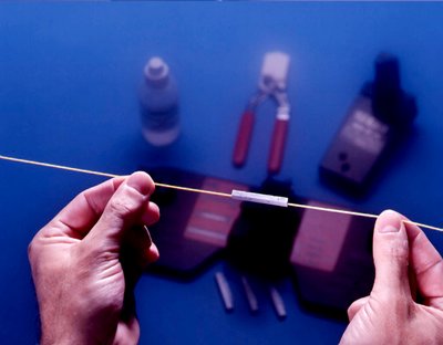
Mechanical splicing (as following picture) aligns and mates the end face of two cleaned and cleaved fiber tip together. It’s a reusable splice. The mechanical splice will have an index matching fluid that eliminates the fiber-to-air interface, there by resulting in less back reflections. Mechanical splices are often used when splices need to be made quickly and easily.
mechanical-splicing
Mechanical Splicing Steps
  • Prepare the fiber. Strip the protective coatings, jackets, tubes, strength members, etc. and only leave the bare fiber showing. Please pay attention to keep the fiber clean.
  • Cleave the fiber. This one is the same to the fusion splicing step. But the cleave precision is as critical.
  • Mechanically join the fibers. This method doesn’t use heat. Simply put the fiber ends together inside the mechanical splice unit. The index matching fluid inside the mechanical splice apparatus will help couple the light from one fiber end to the other. Older apparatus will have an epoxy rather than the index matching fluid holding the cores together.
  • Protect the fiber - the completed mechanical splice provides its own protection for the splice.
Which One Should You Choose?
To decide which fiber splicing method you should choose, you may take two important factors into consideration. First, it’s the cost. Mechanical splicing has a low initial investment ($1,000—$2,000) but costs more per splice ($12-$40 each). While the initial investment is about at least $15,000 and per splice cost is about $0.50 - $1.50. Second, it’s the performance. Fusion splicing offers a high degree performance of lower loss and less back reflection than mechanical splicing.
By the comparison of the cost and performance of two methods, now you know which one is suitable for your applications. If you have enough money and need more precise alignment for lower loss, you could buy a fusion splicing machine. If you just have a small budget and should make a quick splice, then you can choose mechanical fiber optic splice.
Originally published at www.china-cable-suppliers.com/

Monday, October 26, 2015

Passive Optical Network Technology

The tremendous growth in IP traffic badly influenced the access network capacity. It’s believed that the copper-based access networks can’t provide either the minimum bandwidth or the required transmission distance for delivering services of voice, data, and video programs. Passive optical network (PON) is seemed as a promising and cost-effective way to solve this problem.
What’s PON?
PON is a telecommunication network that uses point-to-multipoint fiber to the end-points in which optical splitters are used to enable a single optical fiber to serve multiple end-points. It does not include any electrically powered switching equipment.
Three Devices in PON
There are three distinct devices in the network (as shown in the following picture): the OLT (optical line terminal), the ONUs (optical network units) or ONTs (optical network terminals) and the splitter. Each one has a necessary function in the passive optical network. PON always works under transmission between the OLT and the different ONT’s through optical splitters, which multiplex or demultiplex signals based on their origin and destination.
PON-devices
  • OLTs are located in provider’s central switching office. This equipment serves as the point of origination for FTTP (Fiber-to-the-Premises) transmissions coming into and out of the national provider’s network. An OLT, is where the PON cards reside.
  • ONU converts optical signals transmitted via fiber to electrical signals. These electrical signals are then sent to individual subscribers. ONUs are commonly used in fiber-to-the-home (FTTH) or fiber-to-the-curb (FTTC) applications. Using different wavelengths for each service makes it possible to transmit high-speed Internet and video services at the same time. Wavelength multiplexing is performed at the central office and a wavelength demultiplexing mechanism is provided at the customer's house.
  • PON splitter is used to split the fiber optic light into several parts at a certain ratio. For example, a 1X2 50:50 fiber optic splitter will split a fiber optic light beam into two parts, each get 50 percent of the original beam.
Advantages of PON
There are many advantages given by the use of fiber and the passive elements that compose the network. The following will tell about the advantages of PON.
  • High bandwidth The bandwidth allowed by systems based on PON can reach the 10 Gbps rate down to the user. The need to increase the bandwidth and the speed is another justification for the use of PON.
  • Long distance A PON allows for longer distances between central offices and customer premises. While with the Digital Subscriber Line (DSL) the maximum distance between the central office and the customer is only 18000 feet (approximately 5.5 km), a PON local loop can operate at distances of over 20 km.
  • Low cost On one hand, the cost of passive elements is low. On the other hand, the installation of these PON elements is much more economic. And it avoids operation and maintenance costs, such as absence of falls or maintenance of the network feeds.
Of course PON has some disadvantages. Compared with an active optical network, it has less range. That means subscribers must be geographically closer to the central source of the data. PON also make it difficult to isolate a failure when they occur. However, these disadvantages can not avoid choosing PON as the best possible configuration. Because it saves the cost of deploying PON networks regarding other two configurations (point to point and active optical network). And the flexibility of the network allows the usage of a channel by a large number of users.
Originally published at www.china-cable-suppliers.com/

Wednesday, October 21, 2015

How to Terminate Fiber Optic Cables?

Since the late 1970s, various connectors and termination methods have been brought to market. Now in the common case, cables are terminated in two ways: use connectors to make two fibers jointed or to connect the fiber to other network gears; use splices to make a permanent joint between two fibers. And for the former method, you may have little confusions to deal with it. So today this paper will teach you how to terminate by taking an example of fiber optic cable using epoxy.
First and foremost, use a proper fiber stripper to carefully slide the jacket off of the fiber to a bare fiber. When you are doing this, be careful that try to avoid breaking the fragile glass fiber. After that, mix the epoxy resin and hardener together and load it into a syringe (If you use the pre-loaded epoxy syringes that are premixed and kept frozen until use, then you don’t do that). And next you must inject the epoxy from the syringe directly into the connector ferrule.
Fiber Stripping Tool
Once you have well prepared the epoxy for your connector, you can insert the fiber cable gently into the terminus inside the connector wall and make the bare fiber core stick out about a half an inch from the front of the ferrule. In the case that your cable is jacketed, you may need a crimping tool, such as Sunkit Modular Crimping Tool, to secure the connector to the jacket and strength the cables. Usually two crimp tools would be perfect to this operation.
Next, you can just wait the epoxy to cure. During this process, in order to make sure the end of the fiber is not damaged while curing, you should place the connected end in a curing holder. And when this is done, just place the cable and curing holder into a curing oven. But you may worry about “wicking” while curing with a conventional oven. All you have to do to avoid that is to make the end face down, which can ensure the epoxy does not come out of the back side of the connector and compromise the strength member of the cable. Remember: your epoxy curing must in accurate times and temperatures.
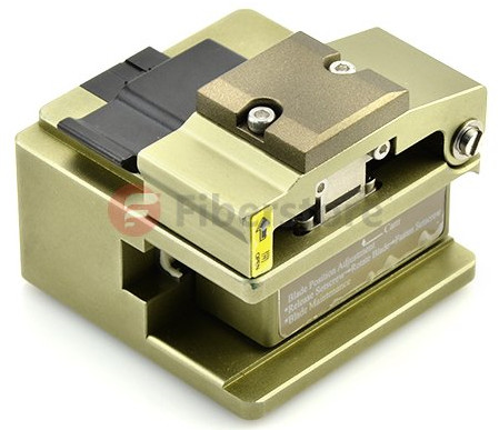
After the epoxy cured sufficiently, fiber cleaver tools will be in use to cleave the excess protruding fiber core so that it could make the fiber close as much as possible to the ferrule tip in case of fiber twisting. Once cleaved, you have to dispose of the fiber clipping. There is a point you should think highly of that you must use a regular piece of tape to retain your fiber debris, or they will easily end up in your skin or even in your eyes or respiratory system.
High Precision Fiber Optic Cleaver
When you finished the fiber cleaved work, you could need fiber polishing tool to remove the excess epoxy from the ferrule tip and buff out any imperfections on the surface of the fiber. A smooth fiber surface can help to reduce the loss of the light. Last, if you have done all the above work, you may move on to the cleaning of the ferrule and fiber tip. After that, the whole termination procedure is done.
If you want to terminate your fiber optic cables by hands, you can follow the above steps. But before you get down to it, you must prepare the tools first that I have mentioned in this paper. All these tools can be found in Fiberstore with good quality and low price. In addition, Fiberstore also can provide the termination tool kits that may be helpful to you. For more details, you could visit www.fs.com.
Article source: http://www.chinacablesbuy.com/how-to-terminate-fiber-optic-cables.html

Tuesday, October 13, 2015

Cable Options for LANs and Data Centers

As the system bandwidth increases, local area network (LAN) campus and building backbones as well as data center backbones are migrating to higher cabled fiber counts. Cable options like loose-tube cable and tight-buffered cable appear for the applications. Later ribbon cable come into the market to meet this need, as they provide the highest fiber density relative to cable size, maximize use of pathway and spaces, and facilitate ease of termination. The following will talk about these kinds of cables.
Loose-tube Cable
Loose-tube cable allows the fibers to lie freely within dry buffered tubes inside the jacket. Because the fibers are loose and not bonded in a ribbon matrix, they do not exhibit any preferential bend and can be flexed in any direction with significantly reduced risk of damage relative to the ribbon cables. Loose-tube cables are much more flexible over the tight bends in the concentrated pathways found in the data center environment.
Loose-tube cable is an design for the LAN applications especially when there are hash environment conditions in outdoors. Many loose-tube cables contain a water resistant gel surrounding the fibers. The gel is good to protect the fibers from moisture, making the cables ideal for high humidity environments. It also enables cable to expand or contract with temperature changes. Loose-tube cable protect the fibers from outside environmental and mechanical damages. That’s why loose-tube cables are widely used in outdoor environments.
Tight-buffered Cable
Meanwhile, there are tight-buffered cables for indoor use. Compared with loose-tube cables, they are better suited for moderate length LAN or WAN connections. Tight-buffered cables offer flexibility, direct connectability and design versatility necessary to satisfy the diverse requirements existing in high performance fiber optic applications.
Instead of using the gel layer, tight-buffered cables have a two-layer coating, plastic and waterproof acrylate. The acrylate keeps moisture away from the cable. Tight-buffered cables are easier to install, because there is no gel to clean up and it does not require a fan out kit for splicing or termination.
Tight-buffered-Cable
Ribbon Cable
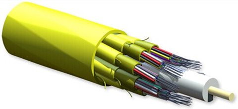
This cable is called ribbon cable because of the looks. It contains a lot of conduction wires lined up side-by-side, to create flat, wide cabling, which resembles a ribbon. The cable design characteristically consists of 12 to 216 fibers organized inside a central tube. It can provide the highest fiber density relative to cable size, maximize use of pathway and spaces, and facilitate ease of termination. Ribbon cables are ideal for situations where space is a factor because they lay flat and take up very little room. This kind of cables have emerged as a primary cable choice for deployment in campus, building, and data-center backbone applications where fiber counts of more than 24 are required.
But the 12-fiber ribbon field terminations was limited. So the innovations such as ribbon-splitting tools, ribbon-furcation kits, and field-installable 12-fiber array connectors were introduce. Then 12-fiber ribbons can be easily terminated with simplex and duplex connectors (such as LC or SC type) or with the MTP array connector. The MTP connector is a 12-fiber push/pull optical connector with a footprint similar to the SC simplex connector. These high-density connectors are used to significantly accelerate the network cabling process, minimize errors, and reduce congestion in patch panels. MTP connectorized ribbon cables allow installers to reduce installation time, minimize clutter and maximize the rack space.
ribbon-cable
All in all, it’s very essential to maximize the use of pathway and spaces, especially in campus and data center backbones. The above cables such as loose-tube cable, tight-buffered cable and ribbon cable play obvious roles for space savings. Fiberstore offers all of these cables and each one has different types of cables. There are also customized service such as optional fiber counts, cable types and lengths etc. So you must choose appropriate one for your network here.
Originally published at http://www.china-cable-suppliers.com/

Wednesday, October 7, 2015

Fibre Channel Testing Strategies

Fibre Channel Introduction
Fibre Channel (FC) is a high-speed network technology that enterprises rely on to transport data to remote sites and store it for protection against potentially damaging natural and human events. It is designed to meet the many requirements related to the ever increasing demand for high performance information transfer. The goals of Fibre Channel are to develop practical, inexpensive, yet expendable means of quickly transferring data between workstations, mainframes, supercomputers, storage devices, displays, desktop computers and other peripherials. Although being called Fibre Channel, its architecture does not represent neither a channel nor a real network topology. It allows for an active intelligent interconnection scheme, called a Fabric, to connect devices. The purpose of the Fibre Channel port is to manage a simple point-to-point connection between itself and the Fabric.
Why Test Fibre Channel?
Fibre Channel aims to carry different types of traffic for applications that require first-rate capabilities of storage. The principal trait of Fibre Channel is the fusion of the network technologies, which allows the communications to have some attributes including high bandwidth, low latency, high data integrity, high connectivity, and large distances, etc. Because of its stringent performance requirements, Fibre Channel requires extensive testing during deployment in order to assure the desired service level.
Fibre Channel Testing Strategies
There are three basic types of test instrument apparatus useful in testing Fibre Channel system. They are two-channel pass-through protocol analyzers, data or pattern generators, or emulators.
The two-channel pass-through protocol analyzer is useful in debugging the correctness of the Fibre Channel transport protocol on the physical links as well as assisting in debugging the user applications running on the link. Besides, it is able to be used to stream data to secondary storage for post run analysis. A pattern generator is able to stress the link’s ability to handle data, send legal and illegal user application data, and perform illegal Fibre Channel operations. Building onto the data generator the ability to respond to link inputs in real-time makes a useful tool for hosting applications under test or for emulating systems to other Devices-Under-Test (DUT). In short, this “emulator” can provide a complete, flexible lab environment in which to stimulate and test a DUT.
In addition to the above testing strategies, there is still another issue to be considered, that is, Fibre Channel should be tested with or without the patch cords? To answer this question, the following factors should be clear first.
As a matter of fact, the main deciding factor for whether to test the Fibre Channel with the patch cords included or to just test the permanent links depends on the specification offered by the end user or their consultant. If needed, the Fibre Channel should be tested with the patch cords. Afterwards, if the question is still unclear after checking the specification, you can consider the fact that patch cords are factory terminated and offer a lower risk of defect and errors. Installing permanent link has much more impact on the performance and insertion loss of the Fibre Channel. Sometimes, testing the Fibre Channel with the patch cords is not logistically feasible as the patch cords are not in place during initial testing before active equipment is installed and up and running. The last factor is that typical insertion loss values or maximum insertion loss values are used to design the Fibre Channel or not. If using typical insertion loss, it is important to know how the patch cords impact the Fibre Channel. Even a negligible loss on the patch cords can have an impact on the design and the Fibre Channel performance. If using maximum insertion loss values, patch cords will not have an impact.
After reading the above description, the answer to Fibre Channel testing with or without patch cords is “it depends”. For the other Fibre Channel testing strategies, each has its own features. when you need to test the Fibre Channel, make clear each strategy and then make the correct decision to maximize your network performance.
Originally published at www.fiber-optic-components.com/

Friday, September 25, 2015

Introduction to Fiber Media Converter

Network complexity and the increasing number of devices on the network are driving higher bandwidth requirements and faster network speeds, as well as forcing longer distance requirements within the local area network (LAN). How to deal with these issues? Media converters present solutions to these issues by providing seamless integration of copper and fiber and different fiber types in enterprise LAN networks. Moreover, media converters can support various protocols, data transfer rates and media types to create a more reliable and cost-effective network. There are many different types of media converters, such as fiber media converters, PoE (Power-over-Ethernet) media converters, etc. This article will mainly introduce fiber media converter.
Fiber Media Converter Overview
A fiber media converter is a simple networking device that makes it possible to connect two dissimilar media types such as twisted pair with fiber optic cabling. Fiber media converters play an important role in interconnecting fiber optic cabling-based systems with existing copper-based, structured cabling systems. They can be divided into fiber-to-fiber media converters and copper-to-fiber media converters. For fiber-to-fiber conversion, the multimode fiber to single-mode fiber and a dual fiber link to single fiber can be converted by using bi-directional data flow, while for copper-to-fiber conversion, the electrical signals used in copper unshielded twisted pair (UTP) network cabling are converted into light waves used in fiber optic cabling.
Fiber-to-Fiber Media Converter
Fiber-to-fiber media converters are capable of connecting different fiber optic networks and supporting conversion from one wavelength to another. They can provide connectivity between single-mode and multimode fiber, as well as between dual fiber and single fiber. Normally, fiber-to-fiber media converters are protocol independent and available for Ethernet and TDM (time division multiplexing) applications.
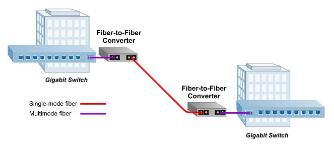
As is shown in the following picture, a fiber-to-fiber media converter is able to extend a multimode network across single-mode fiber with transmission distance up to 140 km. In this application, two Gigabit Ethernet switches equipped with multimode fiber ports are connected by using a pair of Gigabit fiber-to-fiber media converters, which convert the multimode fiber to single-mode and enable the long distance connection between the switches.
fiber-to-fiber media converter

Copper-to-Fiber Media Converter
Copper-to-fiber media converters integrate fiber into a copper infrastructure and make it possible to migrate a local network to fiber while extending the productive life of existing infrastructure. Moreover, they provide connectivity for Ethernet, Fast Ethernet, Gigabit and 10 Gigabit Ethernet devices. Also, they are able to perform 10/100, or 10/100/1000 rate switching and enable the integration of equipment with different data transfer rates and interface types into one seamless network.
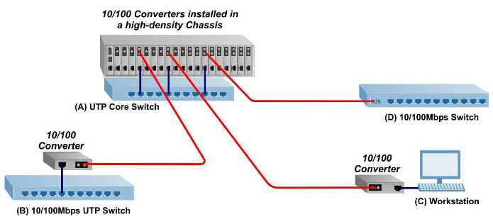
As can be seen from the following diagram, 10/100 media converters are installed in a redundant power chassis for high-density fiber distribution from UTP switch equipment (A) at the network core. A UTP workgroup switch (B) is connected via fiber to the network core with a standalone 10/100 media converter. Another 10/100 converter enables fiber connectivity to PU UTP port in a fiber-to-desktop application (C). An Ethernet switch (D) is connected directly via fiber to the media converter module at the network core.
copper-to-fiber media converter

To sum up, fiber-to-fiber media converters are ideal solutions for the conversion between multimode and single-mode fibers and then increase the transmission distance. Copper-to-fiber media converters are simple and inexpensive solutions for matching copper ports to fiber infrastructure. Fiber media converters are flexible and cost-effective devices for implementing and optimizing fiber links in all types of networks. Fiberstore has various fiber media converters. It is an excellent choice for you.
Originally published at www.fiber-optic-components.com/

Friday, September 18, 2015

40 Gigabit Ethernet Solution


40 Gigabit Ethernet is a standard that enables the transfer of Ethernet frames at speeds of up to 40 gigabits per second (Gbps), allowing 40 Gigabit Ethernet-enabled equipment to handle traffic at the aggregation and core layers. It satisfies the greater demands for faster data transmission and higher bandwidths. Thus, the business case for 40 Gigabit Ethernet is becoming inescapably compelling although 10 Gigabit Ethernet is still making its way into data center. A right and cost-effective solution for 40 Gigabit Ethernet is very necessary for all users who want to migrate to 40 Gigabit Ethernet.
40 Gigabit Ethernet Solution
The picture above is the summary about 40 Gigabit Ethernet, explaining significantly that cables and transceivers are the basis of the whole solution. And actually, they are also the main cost of the item. Next some types of 40 Gigabit Ethernet cables and 40 Gigabit Ethernet transceivers will be introduced in details.
40 Gigabit Ethernet Cables
The cable applied in 40 Gigabit Ethernet can be optical fiber or copper cable. The copper cable for 40 Gigabit Ethernet is designed for short reach, up to at least 7 m. As to optical cable, there are two types: singlemode cable and multimode cable. The transmission distance of multimode cable for 40 Gigabit Ethernet can be up to 150 m, which is much shorter than the transmission distance of singlemode cable (It can be up to 10 km). Generally, the common used types are OM3 and OM4 multimode cables in that its reach supports a wider range of deployment configurations compared to copper solutions, and the cost is lower compared to singlemode solutions.
What is more, the MPO (Multi-Fiber Push On)/MTP (Multi-fiber Termination Push-on) cable is considered the best solution for 40GbE. It can connect the multimode transceivers to support the multifiber parallel optics channels. For 40 Gigabit Ethernet, we can use 8 fibers MPO/MTP harness cables or 12 fibers MPO/MTP trunk cables. The former is to directly connect a QSFP port to other 4 SFP+ ports. The latter is to directly connect one QSFP port to another QSFP port. Here is a picture to help you know it clearly.
MTP Cable
40 Gigabit Ethernet Transceivers
According to different standard form factors, 40 Gigabit Ethernet transceivers can be divided into different types, such as CFP transceiver, CXP transceiver and QSFP transceiver, ect.
CFP transceiver, which has 12 transmit and 12 receive 10-Gbps lanes, can support one 100 Gigabit Ethernet port, or up to three 40 Gigabit Ethernet ports. This module is used for 40GBASE-SR4, 40GBASE-LR4. The former is based on 850nm technology and supports transmission over at least 100m OM3 parallel fibers and at least 150m OM4 parallel fibers, while the latter is based on 1310nm , coarse wave division multiplexing (CWDM) technology and supports transmission over at least 10km on singlemode fiber.
CXP transceiver also has 12 transmit and 12 receive 10-Gbps lanes as well as CFP transceiver, supporting one 100 Gigabit Ethernet port or up to three 40 Gigabit Ethernet ports. Compared with CFP transceiver, the size of it is much smaller. And it is mainly designed for the high-density requirements of the data center, serving the needs of multimode optics and copper.
QSFP transceiver provides four transmit and four receive lanes to support 40 Gigabit Ethernet applications for multimode fiber and copper today. The size of it is the same with CXP transceiver. It is mainly designed to support Serial Attached SCSI, 40G Ethernet, PCIe, 20G/40G Infiniband, and other communications standards.
Fiberstore 40 Gigabit Ethernet Solution
Fiberstore can offer customers 40 Gigabit Ethernet connectivity options for data center networking, enterprise core aggregation, and service provider transport applications. Since the products are all in good quality and low price, it may be the best choice for you to deploy the network.
Originally published at http://www.chinacablesbuy.com/