Wednesday, February 24, 2016

Preparation for 40G/100G Migration

10G is now common in large enterprises. New network trends continue to drive the demand for high-speed Ethernet, such as the virtualization trend, network storage trend, I/O convergence trend, and data center network aggregation trend. So 40G and 100G as well as corresponding equipment are introduced into the market. The migration from 10G to 40G/100G is inevitable.
IEEE and TIA Standards
Before planning for migration to 40G/100G network, we should better know well about high-speed Ethernet. The following will talk about it from the side of standards. Because structured cabling systems design is always guided first by standards. The standards for 40G and 100G are significantly different from previous generations; active equipment and how information is transmitted are unique.
First, it’s IEEE standards. IEEE creates the standards that define performance parameters. IEEE 802.3ba 40Gb/s and 100Gb/s Ethernet is the only current standard that addresses the physical layer cabling and connector media maximums for 40/100G fiber channel requirements. IEEE 802.3ba-2010 standard was approved at the June 2010 IEEE Standards Board meeting. The standard is shown in the following table.
40G/100G Using MPO/MTP Interface
Second, it’s TIA (Telecommunications Infrastructure Standard). For data centers, TIA defines how to apply the parameters to structured cabling systems. It establishes design criteria including space and layout, cabling infrastructure, tiered reliability, and environmental considerations. The standard recommends using the highest capacity media available to maximize infrastructure lifespan.
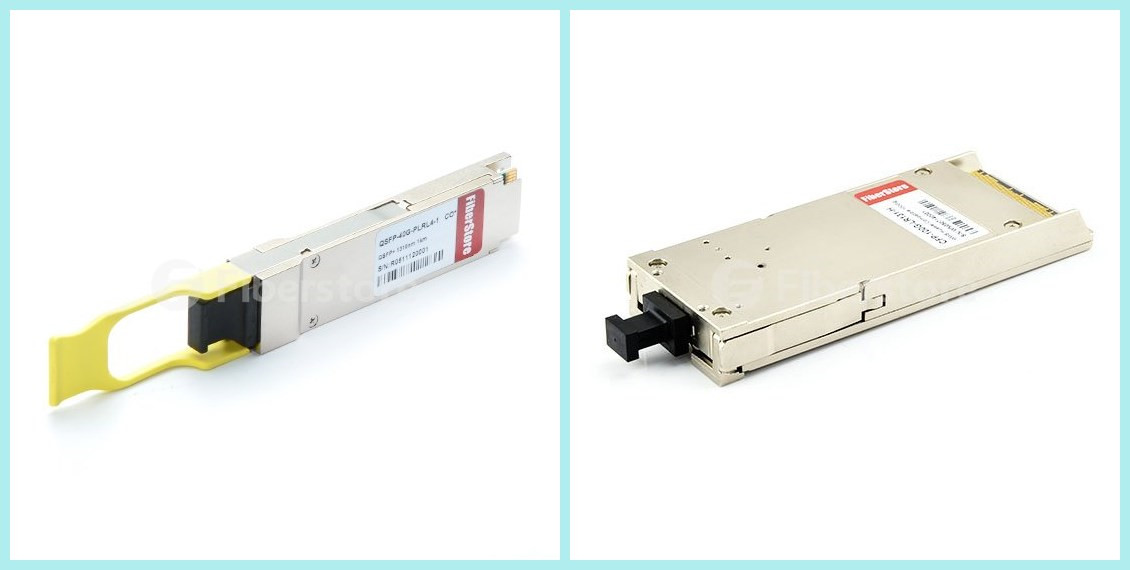
1G and 10G networks use GBIC (Gigabit interface converter). For example, generally the transceiver SFP+ (small form-factor pluggable) is for 10G network. Later the fiber connectivity in high-speed active equipment becomes condensed and simplified. Transceivers for 40G and 100G are QSFP (quad small form-factor pluggable), CFP and CXP (100G form-factor pluggable). MPO/MTP is the designated interface for multimode 40/100G, and it’s backward compatible with legacy 1G/10G applications as well. Its small, high-density form factor is ideal with higher-speed Ethernet equipment.
MTP/MPO-Fiber-Optic-Connector
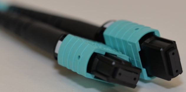
Figure1. MPO/MTP Connector
40G and 100G Ethernet employ parallel optics. Data is transmitted and received simultaneously on MTP interfaces through 10G simplex transmission over each individual strand of the array cable.
After introducing some basics of the high-speed Ethernet, we’ll discuss the structured cabling system of migration to 40G and 100G networks in the simplest and most-effective way.
12- or 24-Fiber Cabling Infrastructure
The system includes configurations for 10G to 40G/100G networks over 12- or 24-fiber MTP cabling. What’s the difference between the two methods? Which one is better? The sections will compare the two from the sides of migration, density and congestion.
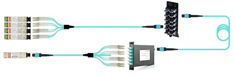
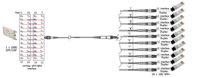
Migration To achieve the migration, components like trunks, harnesses, array cords, modules, and adapter plates are needed. With the 40G 12-fiber legacy configurations, a second trunk and another set of array harnesses will be needed to achieve 100% fiber utilization (as shown in Figure 2). For 100G, it also needs these additional components with 12-fiber legacy configuration. But with 24-fiber trunks, a single cable can support a 1G-100G channel and simplify network upgrades immensely (as shown in Figure 3). When equipment is upgraded, there is no need to install new trunks. In addition, limiting changes can reduce the inherent risks to network security and integrity.
12-fiber-cabling
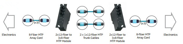
Figure2. 12-Fiber Cabling
24-fiber-cabling
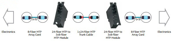
Figure3. 24-Fiber Cabling
Density The higher density connectivity, the more rack space for active equipment. Thus less floor space is needed. In this way, 24-fiber cabling has the obvious advantage. If the active equipment is configured for 24-fiber channel/lane assignments, there will be twice as as many connections with the same number of ports compared to 12-fiber.
Congestion The more connectivity you are able to run in the same footprint, the more crowded it can become at the rack or cabinet. Fewer trunks reduce cable congestion throughout the data centers. Using 24-fiber MTP trunks for the cable runs will save half the number of cables versus 12-fiber in the network. Runs carry a lighter load, fibers are easier to manage, and improved airflow reduces cooling costs. So 24-fiber MTP trunks offer a huge benefit.
Conclusion
The high-speed network will become more and more popular. It’s very important to know something about the migration to 40G/100G. To upgrade your network, 24-fiber MTP will be a better fiber cabling choice compared with 12-fiber. Do you prepare well for the great migration?
Originally published at www.fiber-optic-equipment.com

Wednesday, February 17, 2016

Which One Will You Choose for Your 40/100G Network, OM3 or OM4?

40G has been widely used in data centers. 100G will also come soon. To meet these high bandwidths, related fiber cables are needed. OM3 and OM4 can be used to transmit parallel optical signal. But what is their difference? Which one will you choose for your network?
Both OM3 and OM4 are laser optimized fiber. Their cores size is 50/125. Connectors are the same and both operate 850nm VCSELS (Vertical-Cavity Surface-Emitting Lasers) transceivers. So the difference lies in the construction of the fiber cable, which means OM4 cable has better attenuation and can operate at higher bandwidth than OM3.
OM3-and-OM4
Attenuation is the reduction in power of the light signal as it is transmitted (dB). Attenuation is caused by losses in light through the passive components, such as cables, cable splices, and connectors. As the connectors are the same, so the difference in OM3 and OM4 performance is in the loss (dB) in the cable. The maximum attenuation of OM3 allowed at 850 nm by the standards is less than 3.5 dB/km, and less than3.0 dB/km for OM4.
Another factor influencing the cable function is dispersion. Dispersion is the spreading of the signal in time due to the different paths the light can take down the fiber. It has two types: chromatic and modal. In multimode fiber transmission, chromatic dispersion is negligible and the modal dispersion is the limiting factor.
The modal dispersion determines the modal bandwidth that the fiber can operate at and this is the difference between OM3 and OM4. Modal bandwidth represents the capacity of a fiber to transmit a certain amount of information over a certain distance and is expressed in MHz*km. The higher the modal bandwidth the more information can be transmitted. The modal bandwidth of OM3 is 2700 megahertz*km while the mod0al bandwidth of OM4 is 4700 megahertz*km. Thus, OM4 allows the cable links to be longer.
Compared with OM3, OM4 has a lower attenuation and operates at a higher modal bandwidth. That means over OM4 less power is lost during the signal transmission and the signal can be transmitted further or through more connectors (which add to the losses). The following table shows the Ethernet distances at 850 nm supported by OM3 and OM4 respectively.

1Gb10Gb40Gb100Gb
OM31000m300m100m100m
OM41000m500m150m150m
So why is the standard for 40G only 100m on OM3 and 150m on OM4 compared to 300m and 500m for 10G? There are two reasons. First, when the IEEE 802 standard was created they decided to create a standard based on “relaxed” transceiver specifications so that smaller and lower cost transceivers could be used. Two functions of 10G transceivers (clock recovery and attendant re-timing) are absent in both QSFP+ (40G) and CFP (100G) devices. Second, the standard allows for transceivers with wider spectral width lasers which increase chromatic dispersion (pulse spreading). The quality of transceivers is also a factor.
Which will you choose for your 40/100G network, OM3 or OM4? Except the transmission distance and the cable costs, there are additional factors to consider such as the number of cross connects required and the mix of 40G port to 40G port and 40G port to 10G port. Because 40G signal is transmitted across eight pairs of fiber each with 10G. Similarly, it is important to take into account the likely location of future 100G equipment and the possible 100G to 100G, 100G to 40G and 100G to 10G connectivity requirement.

Originally published at www.fiber-optic-components.com

How to Upgrade to 40/100G for Virtualized Data Center and Campus Network?

40/100G Gigabit Ethernet has come into market as aggregation of 10G Ethernet link. With its high data rates transmission speed, virtualization becomes an inevitable trend, like the virtualized data center and virtualized campus. 40/100G is rapidly gaining traction as a key foundation for building the next generation of virtualized data center and campus environments. Now advantages brought by 40/100G as well as its promises as an interconnect option among data centers and campuses become more and more obvious. To make full use of these virtualized environments, the original network infrastructure should be upgraded to meet 40/100G network capacity.
Data Center Virtualization
Data center virtualization is end-to-end virtualization, including server virtualization, storage virtualization, and network virtualization, and have many diverse benefits. Virtual machines and networks can be quickly and nimbly deployed. Their energy efficiency and capacity can dynamically scale to meet the demands of variable workloads without wasting resources. Disaster recovery is faster, and both initial and ongoing costs can be lower than those of traditional non-virtualized approaches.
To upgrade to the virtualized data center, there are a number of design and operational challenges. One of the most conspicuous challenges is to provide enough bandwidth for the applications of today and the foreseeable future. With converged network technologies, 10GbE, which is becoming a good choice for server access networks, is also good for a storage access network as well. As 10GbE at the access layer, 40/100G is recommended for aggregation and core layers of networks in data centers. Then 40/100G removes the constraints that have previously prevented virtualized data centers from fulfilling their maximum potential.
Campus Virtualization
Video gains more applications in campus networks. But video applications are more than just video conferencing or video streaming. It also includes desktop high definition video, video phone, enterprise TV, IP video surveillance and other video generation and sharing. Another emerging trend in the campus network is “bring your own device”. These applications create pressure on a campus’s distribution and core networks. It’s a must to upgrade to high bandwidth network.
Fiber Cabling Solutions for 10G to 40/100G Migrations
To achieve virtualized data center and campus network, high performance and high-quality fiber solutions are needed. Migrating from 10G (that uses two fibers in either a SC duplex or a LC duplex connector) to 40G and 100G will require a lot more fibers and a different type of connector. The way that optical fiber cabling is deployed for 10G can facilitate an easier migration path to 40G and 100G.
One of upgrading methods from 10G to 40G is to connect four 10Gb/s SFP+ transceiver to a 40Gb/s QSFP+. This requires a QSFP fanout cable MPO/MTP (female) to 8LC. Fiberstore provides several kinds of QSFP transceivers with MTP/MPO connectors, which can connect the 40GBASE module to four 10GBASE optical interfaces, such as QSFP-40G-SR4, QSFP-40G-CSR4, QSFP-40G-PLRL4, QSFP-40G-LX4.
For example, the following picture shows the migration from 10G to 40G data center. The 40GBASE-PLRL4 module to four 10GBASE-LR optical interfaces is connected via our female MTP to 8 single-mode fan-out fiber cables with 4 duplex connectors. In this link solution, an MTP to 8LC conversion module and harness cable are used.
10G-to-40G
There are also some options to achieve the migration from 10G to100G transmission. 100G Ethernet has 10 lanes of 10Gb/s to deliver 100Gb/s connectivity. This configuration uses two 12-fiber MPO trunk cables for the connectivity (as shown in the following picture). Another method is to use a 24-fiber MPO cable to connect two 12-fiber MPO fanouts.
10G-to-100G
Conclusion
40/100G network will be soon adopted into the virtualized data centers and campus networks widely because of the high-bandwidth connectivity. For upgrading from 10G to 40/100G network, Fiberstore offers relative 40G transceiver modules, 100G transceiver modules, MTP/MPO cables, conversion modules and the most cost-effective and high-performance connecting solutions.
Originally published at www.fiber-optic-components.com/

Thursday, February 4, 2016

Ribbon Cable for 40G/100G Data Center

Today many factors drives the need for high data rates, such as virtualization, convergence and high-performance computing environments, etc. So more and more servers, routers and network switches will be added to 40G/100G data centers to handle the increased data traffic. Thus, the optical fiber installation needs migration. But what kind of cable is the most suitable for 40G/100G data centers? To answer this question, we have to learn some thing about one of the connectivity equipment–40G/100G transceivers.
Fiber Optical Transceivers
Different data rates need different transceiver modules. There are SFP (small form-factor pluggable), SFP+ modules for 1G and 10G network, and QSFP+ (quad small form-factor pluggable), CFP (centum form-factor pluggable ) for 40G and 100G network. All of theses transceivers have various types according to form factor. For example, 40GBASE-SR4 and 100GBASE-SR4 (as shown in the following picture) are most often used for 40G and 100G. It uses 4 parallel fibers for transmission and 4 lanes.
40G-transceiver
MPO/MTP Connectors
MPO/MTP connectors are the most prevalent connector type used in the system. Standard 12-fiber MPO are configured. 4 fibers are used for transmission and 4 fibers are used for receive function. The other 4 fibers in the middle are left unused of “dark” fibers.
However, this method may cost more because the fibers are not fully used. If upgrade the system to 100G with a similar 4x25Gbs scheme, the same fiber arrangement can be used. By using conversion harness or interconnect modules, all 12 fibers of a ribbon can be utilized until the interconnection with optical modules is required. The use of ribbons allows for easier connection (less opportunity to cross fibers in an MPO connector), and perhaps more importantly, achieves easier polarization continuity regardless of the polarity method selected for the system.
Comparison Between Ribbon Cable with Armored Versions
Before installing cables, several factors should be considered to decide the cable design. The following will compare ribbon cable with armored versions from the sides of fiber count, cable size, ruggedness of design, and cost.
ribbon-cable
The fiber density is a very attractive feature of these cables especially as fiber counts increase in the data center. A 48-fiber cable ribbon design the outside diameter is about 40% of armor design cable of the same fiber count.
Besides, the cable diameter is also important because the cable is often installed in a conduit system. If the installed cable diameters in the conduit are very high, then the cable installation will be problematic. Maybe the installed cables will be damaged. In comparison, to install 3 armored cables and 3 ribbon cables in a conduit respectively, the amount of “headroom” for the installation using a ribbon cable design is evident.
Of course, except the cable size, there are other factors to determine the cable construction. For example, every cable installation is not the same length or has the same number of bends at the same angles. Installation methodologies are different and depending on the length of cable, its weight, tensile strength must also be taken into consideration. Ribbon cables are flexible and strong and less likely to cause problems during the cable pull process.
At last, the cost is often considered for every installation. The ribbon cable is very cost effective with high fiber counts. For ribbon cables, the fiber counts can be 8, 12, 24, 36, 48 and 72 and easily terminated with MPO/MTP connectors.
Conclusion
Ribbon cables have been used in the network for more than 20 years. The above content obviously shows their advantages of fiber density, size and cost. They are specially suitable for 40G/100G data center builds. In the long run, the ribbon cables are good for future data rate expansion.
Originally published at www.fiber-optic-equipment.com/